DOIT ESP32-32E and 32UE: Module Wiring and First Program
Setup, programming checks, troubleshooting and documentation for DOIT ESP32-32E and 32UE.
On this page
Choose the correct modulePrepare power and programming connectionsEnter download modeBuild and upload the first programTest wireless operation nextIf the first upload failsModule manualsRelated productsOfficial references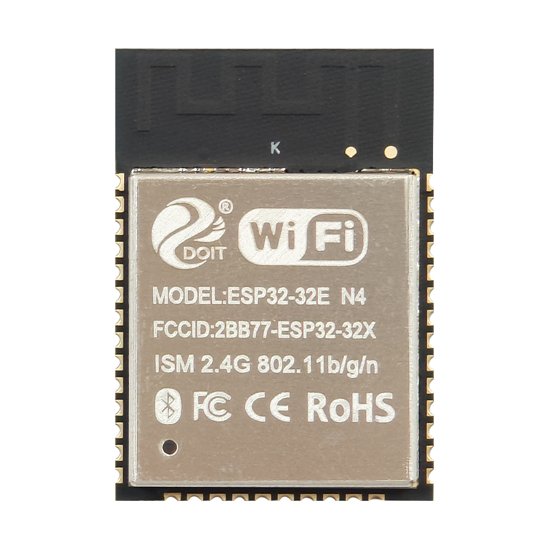
This page covers original ESP32-based DOIT 32E and 32UE modules, not S3 or C3. Retain the exact model and memory selection when choosing the footprint and firmware settings.
Choose the correct module
The 32E manual identifies a PCB antenna. Check the 32UE antenna arrangement in its own manual. A bare module needs a carrier and serial programming interface. Select esp32, not esp32s3, as the build target.
Prepare power and programming connections
| Connection | Before power-on |
|---|---|
| Module supply | Regulated 3.3 V to the supply pad; common ground. Follow the exact minimum-system diagram and decoupling requirements. |
| UART TX / RX | 3.3 V TTL adapter TX to module RX, adapter RX to module TX. Match pad numbers from the exact module drawing. |
| Enable / reset / boot | Use the target-specific instructions below. A GPIO number is not a module pad number. |
| Antenna | Fit the specified external antenna where required; keep a PCB antenna clear of surrounding copper and metal. |
Do not feed USB 5 V into a bare module supply pad. A carrier may accept USB power through its regulator; this does not change the module I/O voltage.
Enter download mode
Hold GPIO0 low while resetting the chip, then release it after download mode is entered. Keep GPIO2 low or floating for download. Do not pull GPIO12 high on a 3.3 V flash design. Use BOOT and RESET/EN buttons only after confirming their functions. Restore the normal boot state and reset after flashing.
Build and upload the first program
- Install and activate ESP-IDF using the official esp32 guide below, choosing a release supporting your chip revision.
- Copy examples/get-started/hello_world from that installed release to a writable folder and open the ESP-IDF terminal there.
- Run the commands below. Replace COM3 with the observed port; on Linux/macOS use the appropriate device path.
- Check that serial output identifies the expected chip and reaches the example output. Exit the monitor with Ctrl+].
idf.py set-target esp32
idf.py menuconfig
idf.py build
idf.py -p COM3 flash monitor
Match flash size in menuconfig to the selected part. Let the build system supply flash offsets instead of copying them from another chip. This workflow has been checked against documentation, not bench-tested on the supplied modules.
Test wireless operation next
Make a separate copy of examples/wifi/scan from the same ESP-IDF release. Set the same target, build and flash it, then check for a nearby compatible access point. Keep this first test independent of displays and sensors.
If the first upload fails
- No port: identify the USB bridge, use a data cable and the matching driver. A bare module has no USB bridge unless its carrier provides one.
- Connecting timeout: check ground, crossed UART wires, enable/reset and boot straps; disconnect peripherals from strapping pins.
- Repeated resets: inspect the 3.3 V rail during startup and radio activity. An adapter output may not supply the required peak current.
- Upload succeeds but the application fails: release the download strap, reset and check target, memory configuration and the serial log.
Module manuals
Related products
| Product / variant family | SKU |
|---|---|
| ESP32-32E WiFi + Bluetooth Dual-mode Dual-core Module | DB36140 |
| Espressif ESP32 Series ESP32-32UE Module, Dual-Mode Wi-Fi + Bluetooth, Compatible with 32-Series Modules | AC41797 |
Official references
Documentation reviewed: 17 November 2026. Hardware instructions are based on the linked manufacturer documents; no physical bench test is claimed.
Share the product link, hardware revision, software version and any error messages.
Contact ESP32S support →