5.0-inch CYD: ESP32-S3 RGB display
Configure an 800 × 480 RGB display, PSRAM and the appropriate touch variant.
On this page
Identify the 5.0-inch boardRGB display and memory configurationFirst power-on and USB checkBuild the 5.0-inch demoS050C control and touch pinsDisplay and touch acceptance checklistLVGL UI developmentFirmware upload and recoveryTroubleshootingDocumentation sources and downloads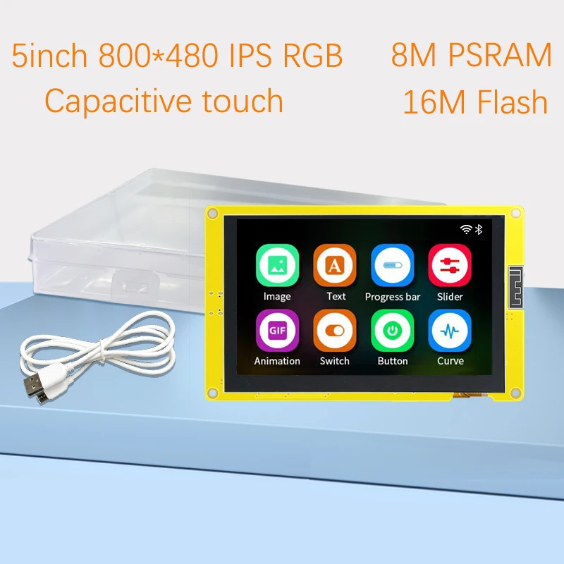
Identify the 5.0-inch board
This listing advertises an ESP32-S3 800 × 480 display with 16 MB flash and 8 MB PSRAM, with touch and non-touch choices. Use the rear board identifier to select a reference profile.
| Printed reference | Variant | Demo environment |
|---|---|---|
| ESP32-8048S050C | Capacitive touch | esp32-8048S050C |
| ESP32-8048S050R | Resistive touch | esp32-8048S050R |
| ESP32-8048S050N | No touch | esp32-8048S050N |
RGB display and memory configuration
The S050C reference uses an ESP32-S3, a parallel RGB display path and GT911 touch. This is not an ILI9341 SPI screen. The board definition supplies 16 MB flash configuration, qio_opi memory type and a PSRAM-backed display buffer.
Keep the matching RGB timings and full data-pin map from the board definition. Copying only the resolution or a 2.8-inch TFT_eSPI setup is not sufficient.
First power-on and USB check
Use a USB data cable. Photograph the working factory screen before replacing its firmware. Connect without extra wiring, identify the new serial port and use the USB checklist if no port appears.
A serial-only sketch checks programming independently of the display. Set the monitor to 115200 baud; it is not a screen test.
void setup() {
  Serial.begin(115200);
  delay(1000);
  Serial.println("ESP32S: serial connection OK");
}
void loop() { delay(1000); }
Build the 5.0-inch demo
Use the PlatformIO workflow. For the confirmed capacitive S050C, select esp32-8048S050C. Keep the project’s LVGL configuration, RGB driver and PSRAM options together. For R/N boards, select their own environment.
S050C control and touch pins
| Signal / configuration | Reference value |
|---|---|
| Backlight GPIO | 2 |
| HSYNC GPIO | 39 |
| VSYNC GPIO | 41 |
| DE GPIO | 40 |
| Pixel clock GPIO | 42 |
| Touch SDA GPIO | 19 |
| Touch SCL GPIO | 20 |
| Touch interrupt GPIO | 18 |
These control pins apply to the named capacitive reference. The full RGB color-data wiring and clock settings remain in the linked JSON profile.
Display and touch acceptance checklist
- Confirm that the demo fills the expected screen area and shows distinct colors.
- Test the center and all four corners. Record rotation and touch-coordinate errors separately.
- For resistive touch, run the project calibration procedure and save the results for that rotation.
- For capacitive touch, confirm controller detection, then check coordinate transforms.
- Reset once after disconnecting the serial monitor and confirm normal startup.
LVGL UI development
First prove that the upstream demo renders and receives touch input. Export a UI using the same LVGL major version as that project. Add one screen at a time and monitor frame-buffer allocation and serial errors. A 16-bit 800 × 480 image contains 768,000 bytes of pixel data before additional buffers or application state.
Firmware upload and recovery
Prefer the project upload command, which uses its generated bootloader, partition table and application layout. For a downloaded binary, follow the release manifest rather than assuming an offset or reusing another board’s firmware.
If connection fails, lower upload speed, close other serial programs and follow the board’s BOOT/RESET procedure. After reset, read the serial log before changing display settings. See the firmware flashing guide.
Troubleshooting
| Symptom | Next check |
|---|---|
| Backlight on, screen blank | Check controller, board profile and display interface before editing application code. |
| Image shifted or unstable | For RGB panels, verify timing and memory settings from the selected profile. |
| Touch does not respond | Check the touch variant and controller independently of the display. |
| Build fails after updating libraries | Restore the project’s pinned dependencies and matching LVGL major version. |
| Upload succeeds but board resets | Read the exception log and confirm target chip, flash layout and PSRAM settings. |
Documentation sources and downloads
References checked October 14, 2026. Board definitions document specific reference hardware; verify the revision on your board. These instructions have not been bench-tested on your individual unit.
Share the product link, hardware revision, software version and any error messages.
Contact ESP32S support →