2.8-inch CYD: ESP32-2432S028R
Identify the CYD revision, configure TFT_eSPI and test the display and resistive touch.
On this page
Identify the 2.8-inch CYDReference hardwareFirst power-on and USB checkArduino display setupOriginal-board pin referenceLVGL and board revisionsDisplay and touch acceptance checklistFirmware upload and recoveryTroubleshootingDocumentation sources and downloads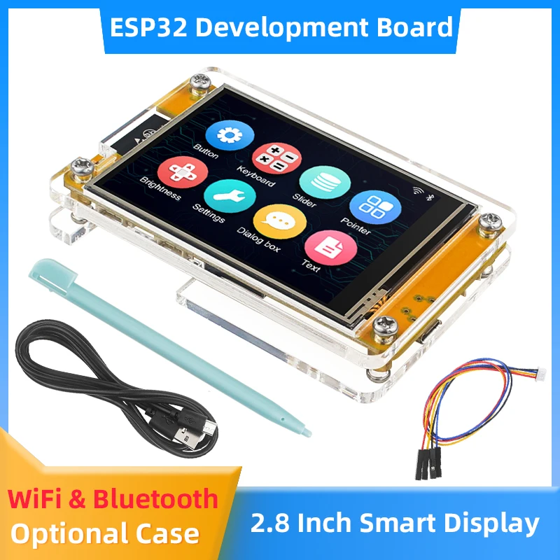
Identify the 2.8-inch CYD
This product is associated with the ESP32-2432S028R family: a classic ESP32 board and a 240 × 320 SPI display. Landscape rotation presents the same panel as 320 × 240.
Use the rear PCB marking and USB connector layout to distinguish the original board from v2/v3 or other controllers. A 2.8-inch screen alone does not identify a compatible firmware.
Reference hardware
| Item | Original ESP32-2432S028R profile |
|---|---|
| MCU | ESP32 (classic family) |
| Flash | 4 MB |
| Display | 240 × 320, ILI9341 SPI reference |
| Touch | XPT2046 resistive reference |
| Board profile | esp32-2432S028R |
First power-on and USB check
Use a USB data cable. Photograph the working factory screen before replacing its firmware. Connect without extra wiring, identify the new serial port and use the USB checklist if no port appears.
A serial-only sketch checks programming independently of the display. Set the monitor to 115200 baud; it is not a screen test.
void setup() {
  Serial.begin(115200);
  delay(1000);
  Serial.println("ESP32S: serial connection OK");
}
void loop() { delay(1000); }
Arduino display setup
For the original ILI9341 model, select ESP32 Dev Module and install TFT_eSPI. Back up its active configuration, then use the CYD project’s User_Setup.h. Ensure that no second setup file selects a different controller. Upload the following simple display test only after configuring the library.
#include <TFT_eSPI.h>
TFT_eSPI screen;
void setup() {
  Serial.begin(115200);
  screen.init();
  screen.setRotation(1);
  screen.fillScreen(TFT_BLACK);
  screen.setTextColor(TFT_WHITE, TFT_BLACK);
  screen.setCursor(12, 20);
  screen.println("ESP32S display test");
}
void loop() { delay(1000); }
Original-board pin reference
| Display signal | GPIO (reference board) |
|---|---|
| MOSI | 13 |
| MISO | 12 |
| SCLK | 14 |
| CS | 15 |
| DC | 2 |
| Backlight | 21 |
On this profile the XPT2046 touch bus uses MOSI 32, MISO 39, clock 25, CS 33 and interrupt 36. Touch and display do not use the same clock/data pins. Keep the bus configuration from the matching example.
LVGL and board revisions
For an LVGL demonstration, use the PlatformIO workflow. Choose esp32-2432S028R, esp32-2432S028Rv2 or esp32-2432S028Rv3 only after checking the physical revision.
Display and touch acceptance checklist
- Confirm that the demo fills the expected screen area and shows distinct colors.
- Test the center and all four corners. Record rotation and touch-coordinate errors separately.
- For resistive touch, run the project calibration procedure and save the results for that rotation.
- For capacitive touch, confirm controller detection, then check coordinate transforms.
- Reset once after disconnecting the serial monitor and confirm normal startup.
Firmware upload and recovery
Prefer the project upload command, which uses its generated bootloader, partition table and application layout. For a downloaded binary, follow the release manifest rather than assuming an offset or reusing another board’s firmware.
If connection fails, lower upload speed, close other serial programs and follow the board’s BOOT/RESET procedure. After reset, read the serial log before changing display settings. See the firmware flashing guide.
Troubleshooting
| Symptom | Next check |
|---|---|
| Backlight on, screen blank | Check controller, board profile and display interface before editing application code. |
| Image shifted or unstable | For RGB panels, verify timing and memory settings from the selected profile. |
| Touch does not respond | Check the touch variant and controller independently of the display. |
| Build fails after updating libraries | Restore the project’s pinned dependencies and matching LVGL major version. |
| Upload succeeds but board resets | Read the exception log and confirm target chip, flash layout and PSRAM settings. |
Documentation sources and downloads
References checked October 14, 2026. Board definitions document specific reference hardware; verify the revision on your board. These instructions have not been bench-tested on your individual unit.
Share the product link, hardware revision, software version and any error messages.
Contact ESP32S support →