ESPP4-A ESP32-P4: Module, DevKit, Wi-Fi & Display Setup
Set up the ESPP4-A module and DevKit: ESP-IDF, Flash/PSRAM settings, UART programming, Wi-Fi, ST7102 display, touch and local technical downloads.
On this page
1. Choose the correct hardware path2. Download the local technical package3. Install ESP-IDF and identify the debug port4. Match Flash and PSRAM settings5. Build the first Wi-Fi example6. Connect and verify Wi-Fi7. Bring up the matching display and touch8. Camera check for the display kit9. DevKit GPIO reference10. Module pad and reserved-pin notes11. Troubleshooting12. License, verification and support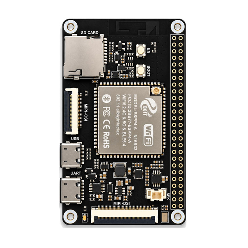
Bring up an ESPP4-A module or ESP32-P4 DevKit one step at a time: identify the package, verify programming, connect Wi-Fi, then add the matching display. This guide follows the supplied DevKit v1.1 reference materials.
1. Choose the correct hardware path
Module only: use a suitable carrier, regulated 3.3V supply, antenna arrangement and programming access. Do not connect a USB cable or 5V directly to the module VDD pads. DevKit: use the UART-DEBUG Type-C connection for the initial programming test. DevKit plus display: the package includes the board, touch display and camera.
View the module, board and display options. The four N/R memory selections on the product page apply to module-only options.
2. Download the local technical package
Extract the ZIP into a simple working path, such as C:/Projects/ESPP4-A on Windows. Keep components/, examples/ and hardware/ together. The archive contains the original supplier files and license notices; its original documentation may contain Chinese.
3. Install ESP-IDF and identify the debug port
Use ESP-IDF 5.5.3 as the documented starting point. Run the Espressif ESP-IDF terminal on Windows, or load the installed export.sh environment on Linux. The first build downloads managed dependencies and requires network access.
Connect a data-capable USB cable to UART-DEBUG, not the separate USB-OTG port. Identify the actual COM port in Device Manager and install the CH340 driver when necessary. On Linux the port may be /dev/ttyUSB0. Do not copy a port name without checking your computer.
4. Match Flash and PSRAM settings
The module-only options are N8R16, N16R16, N8R32 and N16R32. N is Flash capacity in MB; R is PSRAM capacity in MB. Record the actual marking before building. The supplied examples default to 16MB Flash. For an N8 module, change Flash size to 8MB and verify the complete partition layout fits before flashing.
The wireless component uses enabled PSRAM in Hex mode and the package-specific clock settings. Keep the supplied sdkconfig.defaults and partition table. Changing defaults after sdkconfig already exists may not change the generated configuration: check idf.py menuconfig. Keep a backup before changing target or partition layout.
5. Build the first Wi-Fi example
From the extracted ESPP4-A project root, enter the component's actual example directory:
cd components/p4_wireless/examples/wifi_cmd
idf.py set-target esp32p4
idf.py menuconfig
idf.py build
idf.py -p COM7 flash monitor
Replace COM7 with your own serial port; Linux users can substitute /dev/ttyUSB0. The target command resets target-dependent configuration, so apply and verify your memory settings afterwards. Exit the monitor with Ctrl+].
If connection fails, hold BOOT, press and release RST, release BOOT, then retry flashing. A power LED alone does not prove that programming or the wireless component is working.
6. Connect and verify Wi-Fi
At the wifi> prompt enter:
scan
sta "your-ssid" "your-password"
info
ping 192.168.1.1 4
Use your own router address for ping. Wait for got ip: before testing traffic. STA and SoftAP are alternative operating modes in this component; simultaneous AP+STA is not supported. BLE uses NimBLE rather than Bluedroid. Do not confuse the module's integrated companion radio with native Wi-Fi inside the P4 chip.
7. Bring up the matching display and touch
Power off before fitting the display ribbon, check the contact orientation and secure the latch. Use the supplied ST7102 4.96-inch 480 × 854 panel and board definition. The touch implementation uses the compatible ST7123 protocol; replacing it with an arbitrary I2C touch driver is not equivalent.
Open a fresh ESP-IDF terminal and, from the project root, run:
cd examples/lcd_lvgl
idf.py set-target esp32p4
idf.py build
idf.py -p COM7 flash monitor
Check Flash settings for the actual board before flashing. Keep the generated board-manager files and dependency versions together. The expected supplier example log is LVGL widgets demo started. Check visible graphics first, then test a slider and button. The package uses LVGL 9; older LVGL 8 projects need their own port rather than copied API calls.
8. Camera check for the display kit
The camera is included in the board/display/camera kit. Check its marking before choosing a driver. The supplied DevKit v1.1 camera example targets GC4023. With power disconnected, seat the ribbon in the matching MIPI-CSI connector, then use examples/camera with the same board definitions. Build and flash for esp32p4 using the actual debug port. Check camera initialization in the serial log before troubleshooting the preview. Do not substitute a 24-pin DVP camera just because the contact count looks similar.
9. DevKit GPIO reference
| GPIO | DevKit v1.1 function |
|---|---|
| 24 / 46 | Display backlight enable / display reset |
| 47 / 48 / 49 / 50 | Touch reset / I2C SCL / I2C SDA / interrupt |
| 35 / EN | BOOT / reset |
| 37 / 38 | UART0 TX / RX through CH340X |
| 39–42 / 43 / 44 / 45 | TF D0–D3 / clock / command / card detect |
| 4 | TF power switch, active low |
| 9 / 10 / 11 / 21 | Optional camera I2C SDA / SCL / reset / MCLK |
This is the reference DevKit assignment, not a generic ESP32 pinout. The camera is included with the display kit; it is not included with module-only or board-only options. Use the schematic for power and connector pin numbering.
10. Module pad and reserved-pin notes
Pad numbers and GPIO numbers are different. The module's VDD pads are 19 and 20; EN is pad 71. The supplier pin table is included below for carrier-board reference.
| Pad | Signal | Pad | Signal | Pad | Signal |
|---|---|---|---|---|---|
| 1 | GND | 25 | DSI_D1_P | 49 | GPIO33 |
| 2 | RF_WF | 26 | DSI_D1_N | 50 | GPIO34 |
| 3 | GND | 27 | DSI_CLK_N | 51 | GPIO35 |
| 4 | GPIO0 | 28 | DSI_CLK_P | 52 | GPIO36 |
| 5 | GPIO1 | 29 | DSI_D0_P | 53 | GPIO37 |
| 6 | GPIO2 | 30 | DSI_D0_N | 54 | GPIO38 |
| 7 | GPIO3 | 31 | CSI_D0_N | 55 | GPIO39 |
| 8 | GPIO4 | 32 | CSI_D0_P | 56 | GPIO40 |
| 9 | GPIO5 | 33 | CSI_CLK_P | 57 | GPIO41 |
| 10 | GPIO6 | 34 | CSI_CLK_N | 58 | GPIO42 |
| 11 | GPIO7 | 35 | CSI_D1_N | 59 | GPIO43 |
| 12 | GPIO8 | 36 | CSI_D1_P | 60 | GPIO44 |
| 13 | GPIO9 | 37 | USB_N | 61 | GPIO45 |
| 14 | GPIO10 | 38 | USB_P | 62 | GPIO46 |
| 15 | GPIO11 | 39 | GND | 63 | GPIO47 |
| 16 | GPIO12 | 40 | GPIO24 | 64 | GPIO48 |
| 17 | GPIO13 | 41 | GPIO25 | 65 | GPIO49 |
| 18 | GND | 42 | GPIO26 | 66 | GPIO50 |
| 19 | VDD | 43 | GPIO27 | 67 | GPIO51 |
| 20 | VDD | 44 | GPIO28 | 68 | GPIO52 |
| 21 | GPIO20 | 45 | GPIO29 | 69 | GPIO53 |
| 22 | GPIO21 | 46 | GPIO30 | 70 | GPIO54 |
| 23 | GPIO22 | 47 | GPIO31 | 71 | EN |
| 24 | GPIO23 | 48 | GPIO32 | 72 | GND |
GPIO14–19 are used by internal wireless SDIO and are not exposed as general-purpose pins. GPIO54 is used for wireless reset. The wireless interface uses SDMMC Slot 1; the reference TF slot uses Slot 0. Avoid repurposing these signals. GPIO34–38 include boot-strapping functions; do not force inappropriate startup levels.
11. Troubleshooting
| Symptom | Next check |
|---|---|
| No serial port | Data cable, UART-DEBUG connector, CH340 driver and actual port selection. |
| Failed to connect | BOOT/RST download-mode sequence, cable and power; disconnect added peripherals. |
| Brownout / repeated resets | Power source, cable resistance and the module's regulated 3.3V supply. |
| esp_wifi_init returns ESP_FAIL | Matching ESPP4-A hardware, unmodified wireless component, supported environment and supplier support; do not bypass authorization. |
| Wi-Fi connects without IP | Keep the supplied initialization order, including creating the STA network interface before wireless initialization. |
| Blank display | Matching panel, ribbon orientation, board definition, backlight GPIO24 and reset configuration. |
| New library compiles but crashes | Restore the supplied version set. The supplier notes esp_lvgl_port ~2.6 for IDF 5.5; clean the build after dependency changes. |
12. License, verification and support
The download preserves the original LICENSE and NOTICE files. Most project material is Apache-2.0; p4_wireless is proprietary and may be redistributed unmodified for matching ESPP4-A hardware under its own license. Do not overwrite its module-authorization eFuse BLOCK_KEY5 or attempt to bypass authorization.
This guide is based on supplier documentation, revision 1e981d9f159a1afb30bd5e41b0137344ce3916a6, reviewed 2026-11-03. We have not performed a physical bench test or locally compiled these ESP-IDF examples. Example outcomes are checks to perform, not a claim that this store tested your individual board.
For help, contact support with the order number, selected option, module marking, PCB revision, software versions and full log.
Share the product link, hardware revision, software version and any error messages.
Contact ESP32S support →