ESP32S Presence Radar — Wiring, Setup & Development
R1.2 female sockets: J2 TX at the top and VCC at the bottom. Inward LD2410C stacking, wiring, setup, enclosure checks and Wi-Fi CSI development limits.
On this page
Overview and kit contentsDevelopment statusHardware and powerR1.2: female sockets and inward radar stackJ2 radar wiringOther interfacesRESET and BOOTStart with radar-only softwareWi-Fi CSI developmentMechanical and manufacturing filesTroubleshootingResources and licence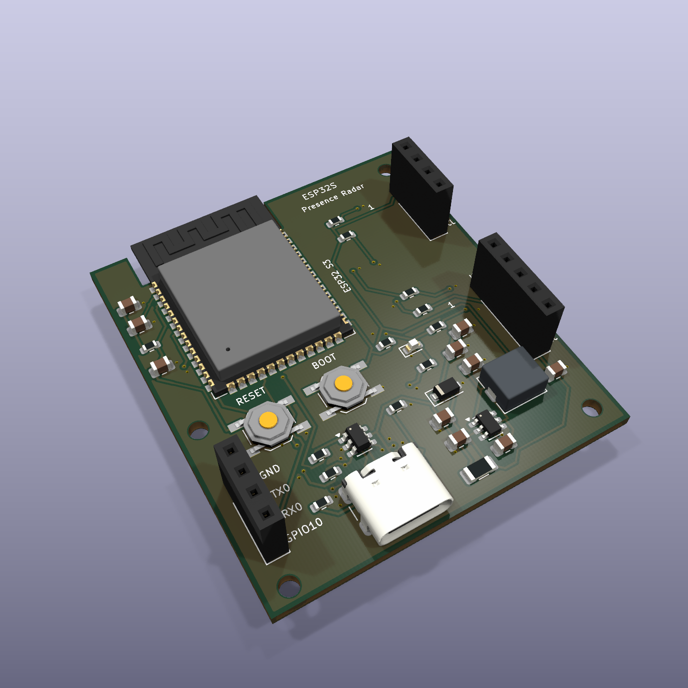
Overview and kit contents
ESP32S Presence Radar R1.2 combines a 45 × 50 mm ESP32-S3 mainboard with an external HLK-LD2410C radar. The USD $29 kit includes the assembled mainboard, radar module and matching connection cable; no enclosure, USB cable or power adapter. Made to order: 5-day production lead time after confirmation, with dispatch after production and checks.
Buy the kit on ESP32S · Open design on GitHub
Development status
This is an R1.2 engineering prototype. Hardware has not yet been powered on or qualified. ERC/DRC and netlist checks pass, but they do not validate power, USB or sensing performance. Complete CSI firmware is not implemented; the ESPHome example is radar-only and uncompiled.
Hardware and power
- ESP32-S3-WROOM-1-N8R8, built-in PCB antenna.
- 5 V USB-C input; AP63203 supplies 3.3 V to the controller.
- LD2410C uses 5 V power and 3.3 V UART logic, default 256000 baud.
- External regulated 5 V supply with 1 A capability is the design target; there is no USB-PD negotiation or CC current sensing.
The supplied radar manual calls for more than 200 mA supply capability for the radar alone. Verify actual voltage at the radar after cable losses. Keep metal, screws and the radar board away from the Wi-Fi antenna clearance region.
R1.2: female sockets and inward radar stack
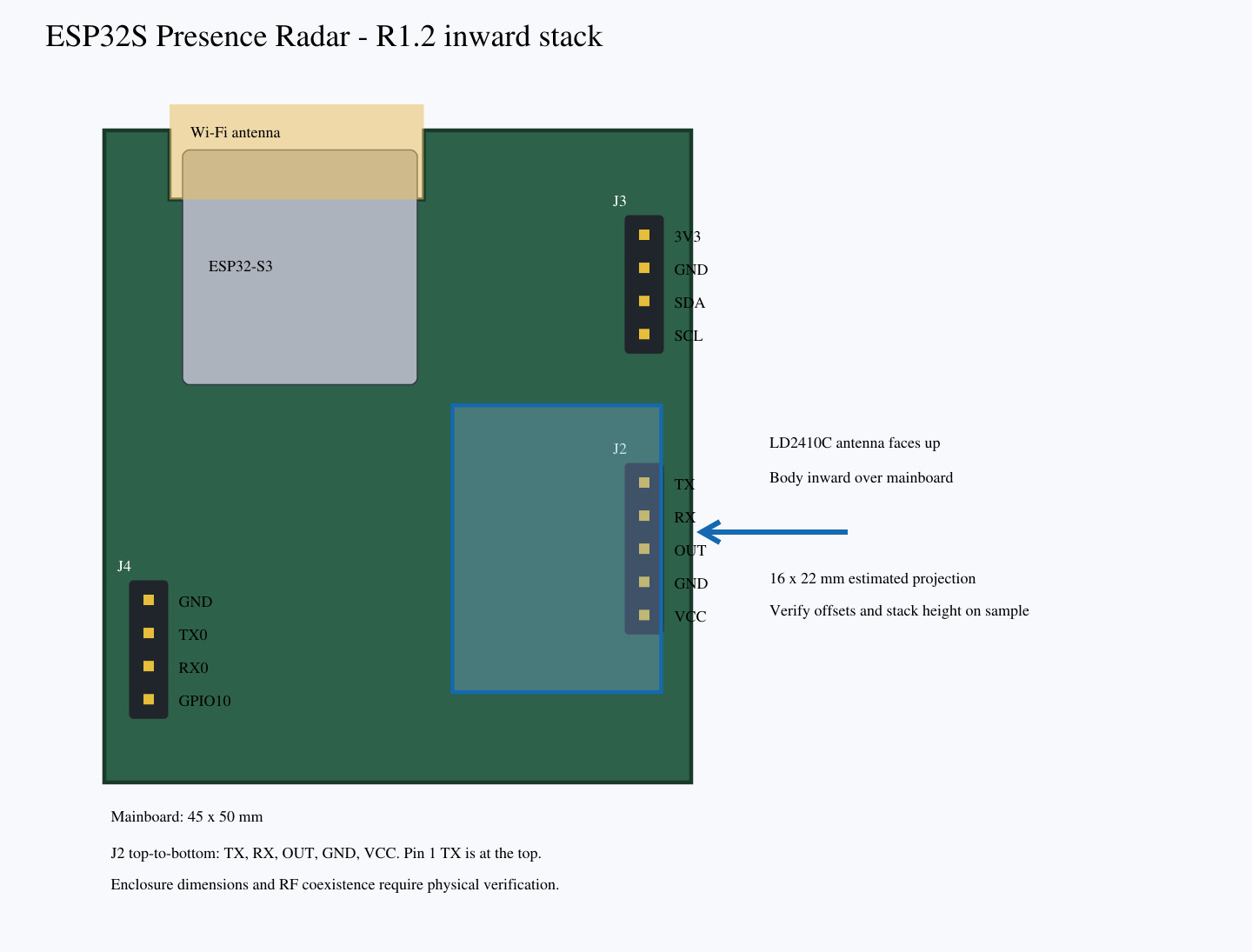
J2, J3 and J4 now use female sockets. J3 is at the upper right; J2 is lower right. Viewed from the component side, J2 runs TX, RX, OUT, GND, VCC from top to bottom. TX is square-pad pin 1 at the top; VCC is pin 5 at the bottom.
The intended direct-plug orientation places the LD2410C antenna face upward and its body inward over the mainboard, helping keep the kit within the mainboard footprint for enclosure planning. The PCB remains 45 × 50 mm. Exact module pin-to-edge offsets, socket and insertion height, underside clearance and final enclosure dimensions must be confirmed on samples. Inward stacking does not prove Wi-Fi/radar coexistence.
The matching cable is included for optional remote mounting. Do not reverse the module: match all five signals before applying power.
Download latest R1.2 KiCad design and manufacturing archive · GitHub project
J2 radar wiring
Disconnect power before wiring. Match signals, not connector orientation. J2 TX/RX names follow the radar's viewpoint.
| J2 pin | Silkscreen | Connection |
|---|---|---|
| 1 | TX | Radar TX → ESP32 GPIO5 (receive) |
| 2 | RX | Radar RX ← ESP32 GPIO4 (transmit) |
| 3 | OUT | Radar OUT → ESP32 GPIO6 |
| 4 | GND | Ground |
| 5 | VCC | 5 V supply |
R1.2 pin 1 TX is at the top of J2, marked by a square pad and a printed 1; pin 5 VCC is at the bottom. The top-to-bottom motherboard socket sequence is TX, RX, OUT, GND, VCC. With the antenna face upward, the module body extends inward above the mainboard. Do not connect 5 V logic UART or RS-232 signals.
Other interfaces
| Interface | Pin definition |
|---|---|
| J1 USB-C | VBUS 5 V; D− GPIO19; D+ GPIO20; GND; CC1/CC2 5.1 kΩ pulldowns |
| J3 I²C | 1 3V3; 2 GND; 3 GPIO8 SDA; 4 GPIO9 SCL |
| J4 debug | 1 GND; 2 GPIO43 TX0; 3 GPIO44 RX0; 4 GPIO10 |
J4 TX0/RX0 follow the ESP32 viewpoint; J4 has no power output. GPIO7 drives the status LED. GPIO35/36/37 are reserved for N8R8 PSRAM.
RESET and BOOT
SW1 RESET controls EN; SW2 BOOT controls GPIO0. To request download mode: hold BOOT, press and release RESET, then release BOOT. Use a USB data cable. UART0 is available for rescue debugging if native USB does not enumerate.
Start with radar-only software
- Download and unpack the complete GitHub design archive.
- Read the engineering notes before first power-up; check assembly and short circuits, then verify 5 V and 3.3 V using a current-limited supply.
- With power removed, connect the radar cable by the J2 pin table.
- Copy firmware/secrets.example.yaml to firmware/secrets.yaml and supply local Wi-Fi credentials.
- Use an ESPHome version supporting ESP32-S3 and LD2410 to validate, compile and upload firmware/radar_baseline.yaml. It has not yet been compile-tested.
- Compare radar presence, moving/still targets, distances and the OUT diagnostic in an empty room and with a person present.
Do not publish secrets.yaml. No pre-flashed firmware or ready-to-use cloud service is promised by this development kit.
Wi-Fi CSI development
Start from Espressif ESP-CSI under ESP-IDF. Choose suitable Wi-Fi traffic/transmitter placement, capture CSI and calibrate an activity detector. Coordinate Wi-Fi communication and CSI channel/packet tasks.
firmware/fusion_reference.py is an executable Python rule reference, not ESP32 firmware or a CSI detector. Radar asserts presence immediately. A valid, calibrated, fresh CSI event may grant one departure grace period of at most 5 seconds; ongoing activity cannot extend it indefinitely. Radar loss results in unknown. CSI alone must not assert presence.
python -m unittest discover -s firmware -p "test_*.py" -vSix reference-rule tests pass. Validate real rooms, static occupants, fans and adjacent-room movement before claiming any accuracy or coverage.
Mechanical and manufacturing files
KiCad 10 source, local libraries, BOM, Gerber, drill and assembly placement files are in the complete design archive. The PCB is 45 × 50 mm with a 19.5 × 5.3 mm top antenna notch. Antenna and USB overhang must be considered for enclosure design. Mounting centres relative to the upper-left board envelope: H1 (2.5, 27.5), H2 (42, 3), H3 (3, 48), H4 (42, 47), in mm.
The radar and cable are separate from the SMT assembly positions. Stock/prices and replacements in the BOM are not verified. Current USB routing uses a two-layer board without controlled impedance and requires actual enumeration and waveform testing.
Troubleshooting
- No serial port: check USB data cable, BOOT/RESET sequence, supply voltage and UART0 debug.
- No radar data: verify 5 V at the module, common ground, crossed TX/RX and 256000 baud.
- False presence: begin with radar-only tuning; check moving objects, mounting position and interference before enabling CSI.
- Unexpected resets: measure supply drop and ripple during Wi-Fi transmission.
Resources and licence
GitHub design and examples · ESP32S purchase page · ESP32-S3 module datasheet
Original hardware: CERN-OHL-P-2.0. Original code/documentation: MIT. Upstream KiCad library licences are retained. Mainboard images are 3D renders; module reference photos do not show the complete kit.
Share the product link, hardware revision, software version and any error messages.
Contact ESP32S support →