
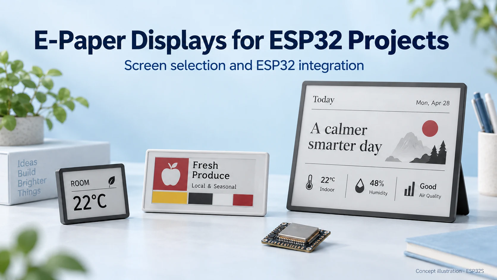
E-Paper Displays for ESP32: How to Choose the Right Screen
Choose an e-paper display for your ESP32 project: compare screen types, raw panels and modules, refresh modes, memory needs and power considerations.
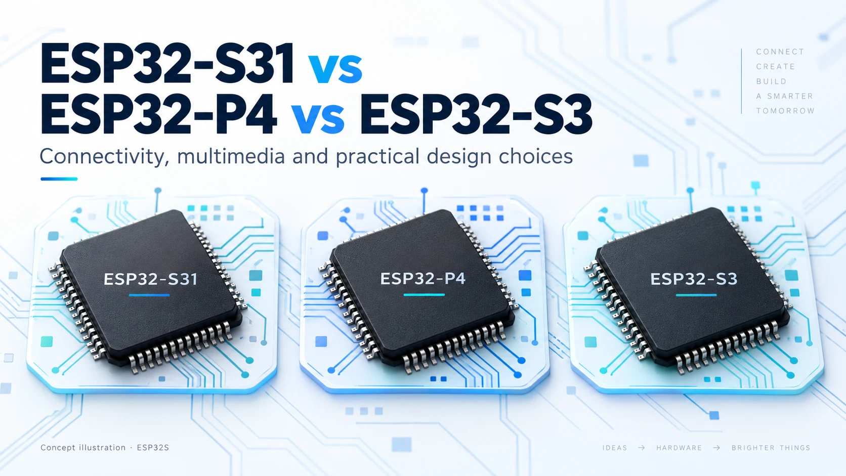
ESP32-S31, ESP32-P4 and ESP32-S3 solve different product-design problems. The right choice depends on your connectivity, display interface, memory budget and software requirements—not simply the highest clock speed.
Technical review: October 15, 2026. ESP32-S31 specifications are preliminary. This is a documentation-based selection guide, not a measured performance benchmark.
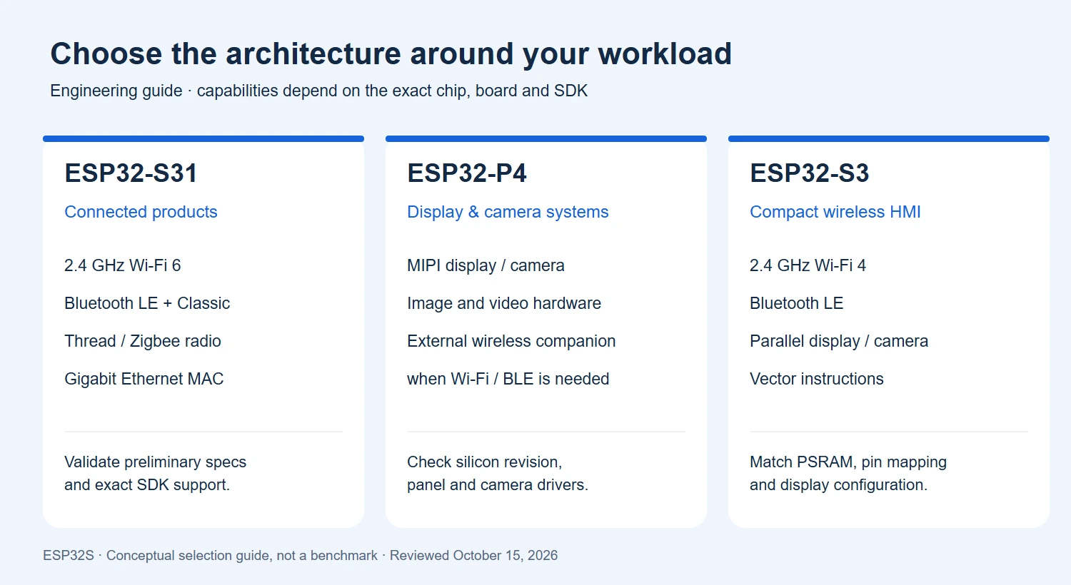
| Feature | ESP32-S31 | ESP32-P4 | ESP32-S3 |
|---|---|---|---|
| Main CPU | Dual-core RISC-V, up to 320 MHz | Dual-core RISC-V, up to 400 MHz on the v3.x series covered by the current datasheet | Dual-core Xtensa LX7, up to 240 MHz |
| Integrated Wi-Fi | 2.4 GHz Wi-Fi 6 | None | 2.4 GHz Wi-Fi 4 |
| Integrated Bluetooth | Bluetooth 5.4 LE and Classic BR/EDR | None | Bluetooth 5 LE |
| IEEE 802.15.4 radio | Yes; Thread / Zigbee applications | No integrated radio | No integrated radio |
| Display / camera direction | Parallel RGB / I8080 LCD and DVP camera | MIPI DSI / CSI, ISP and multimedia acceleration | Parallel LCD / camera interfaces |
| Memory planning | 512 KB HP SRAM; external PSRAM interface | 768 KB HP L2 memory; PSRAM configuration depends on the exact part | 512 KB SRAM; external flash / PSRAM configuration varies |
Specification sources: ESP32-S31 datasheet, ESP32-P4 datasheet and ESP32-S3 product overview. Maximum clocks are ceilings, not directly comparable application-performance scores. Check the exact P4 silicon revision; do not apply the v3.x figure to every older board.
ESP32-S31 combines Wi-Fi 6, Bluetooth LE, Bluetooth Classic and an IEEE 802.15.4 radio. Espressif also lists a 1000 Mbps Ethernet MAC and image-processing hardware. An Ethernet MAC still needs a suitable external PHY and board-level circuitry; it does not mean a complete Ethernet port is integrated. Its Wi-Fi operates at 2.4 GHz, not 5 GHz. See the official ESP32-S31 overview.
For a gateway or connected panel, this combination may reduce the need for separate connectivity devices. However, a radio feature does not automatically mean every protocol stack, audio profile or concurrent operating mode is ready in your chosen firmware release. The reviewed S31 datasheet is preliminary v0.5, and the product page describes framework support in future terms. Verify a working example for your exact application before selecting the production platform.
ESP32-P4 provides MIPI camera and display interfaces, an image signal processor, H.264 encoding and graphics-related acceleration. It is a strong candidate when your architecture starts with a camera pipeline or a MIPI display. Espressif describes connecting a separate wireless companion through interfaces such as SDIO, SPI or UART, using solutions including ESP-Hosted or ESP-AT. See the official ESP32-P4 overview.
A P4 development board with Wi-Fi is not evidence that the P4 chip contains Wi-Fi. Inspect the board schematic and identify the companion radio. Your system budget then includes its power supply, firmware, host transport, antenna placement and update strategy. Test the host-to-radio data path alongside the GUI or camera workload, rather than evaluating each subsystem in isolation.
ESP32-S3 combines a dual-core Xtensa processor with 2.4 GHz Wi-Fi and Bluetooth LE. Its vector instructions support signal-processing and neural-network software optimizations; they should not be presented as a standalone NPU or an invented TOPS rating. Bluetooth LE also does not imply Bluetooth Classic audio support. These distinctions are documented in Espressif’s S3 overview.
For a touchscreen controller, start with an actual board and panel configuration that has a working example. Our 5-inch ESP32-S3 display guide is a useful reference for board-specific setup. A firmware image for one display board is not automatically suitable for another board using the same SoC: touch controllers, backlight pins, panel timing and memory configurations can differ.
Consider an 800 × 480 RGB565 framebuffer. At two bytes per pixel, one full framebuffer requires 768,000 bytes (750 KiB). Two full buffers require 1,536,000 bytes, approximately 1.46 MiB, before allocating the GUI heap, images, networking buffers or application data.
This calculation is a memory estimate, not a guaranteed GUI requirement: partial rendering and other buffering strategies change the allocation. It nevertheless explains why you should check PSRAM capacity, bandwidth and driver requirements early. A higher CPU clock cannot fix an incompatible panel interface or an insufficient memory budget. Measure your actual screen transitions, touch latency and network activity together.
These are engineering starting points. None of the three is a drop-in replacement for another. Changing the SoC can require a new PCB, pin mapping, boot configuration, firmware target and peripheral drivers.
Explore the ESP32S Wiki and firmware flashing guide for practical setup information. If you need help turning a prototype into a custom product, our PCB design service can support the hardware work; contact us to discuss ESP32 firmware development and production flashing requirements.
Sources checked on October 15, 2026: ESP32-S31 preliminary datasheet v0.5; ESP32-P4 pre-release datasheet v0.7, covering v3.x; and the official product pages linked above. Recheck these documents before freezing a production design. Feature availability depends on the exact silicon, hardware implementation and software release.
Illustrations: original conceptual cover and an ESP32S selection diagram. The cover is not a photograph of production chip packages. No comparative hardware benchmark was performed for this article.

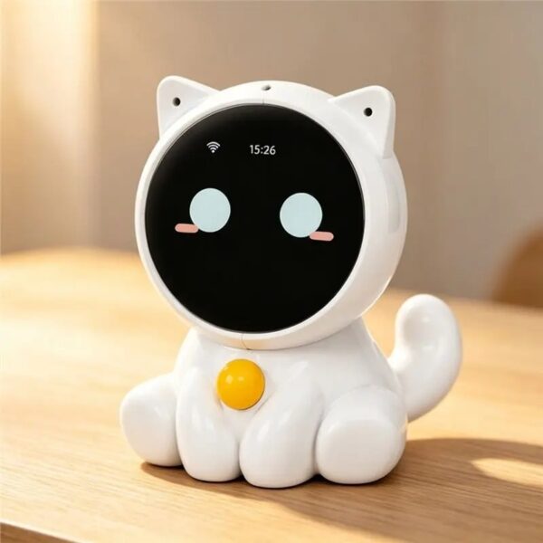
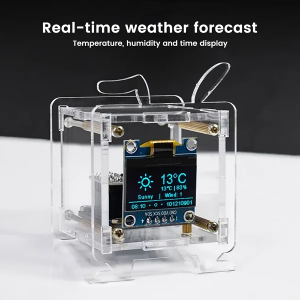
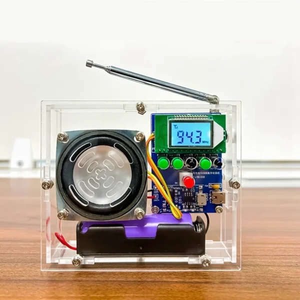
Choose an e-paper display for your ESP32 project: compare screen types, raw panels and modules, refresh modes, memory needs and power considerations.
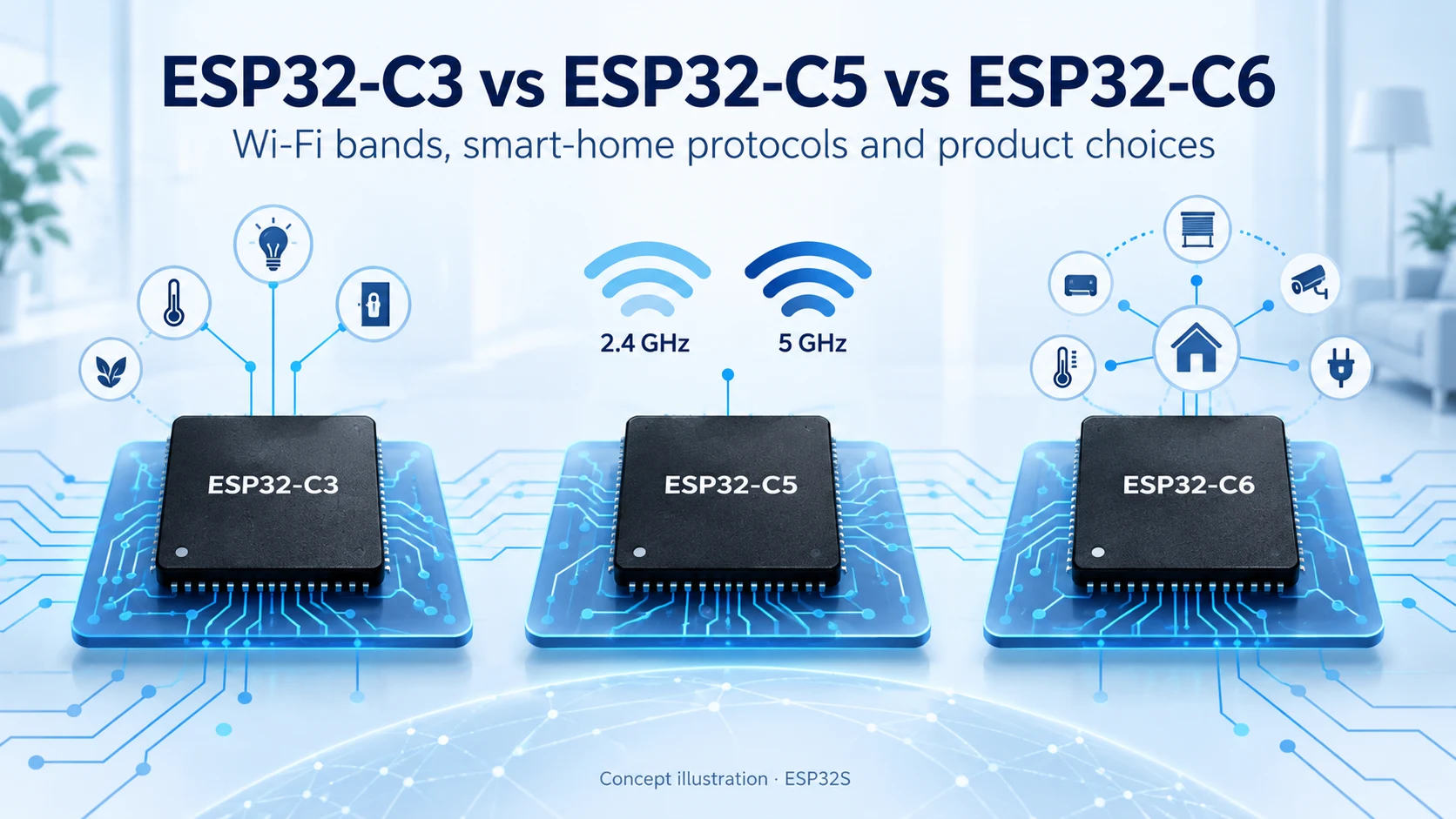
Compare ESP32-C3, ESP32-C5 and ESP32-C6 for Wi-Fi bands, Bluetooth LE, Thread, Zigbee, memory and Matter product design. Find the right connectivity for your project.
Compare ESP32-S3 and ESP32-C3 for CPU, memory, displays, cameras, USB and wireless connectivity. Practical advice for choosing your next connected product platform.
Compare ESP8266, ESP8285 and ESP32-C3 for Wi-Fi, Bluetooth LE, flash, security and migration. A practical guide for existing designs and new connected products.
Most people meet us through the store. They buy an ESP32-C3 Supermini board or a camera module, it ships, and
Every ESP32 product starts on a dev board. That is the right way to start — you get a working
No account yet?
Create an Account