
ESP32 CYD Pinout: ESP32-2432S028R GPIO & Wiring
This pinout guide focuses on the ESP32-2432S028R 2.8-inch CYD. Identify the PCB revision before using a pin table: a different display controller, capacitive-touch variant or ESP32-S3 board can require different wiring and software. Start with the 2.8-inch CYD setup guide for the matching hardware.
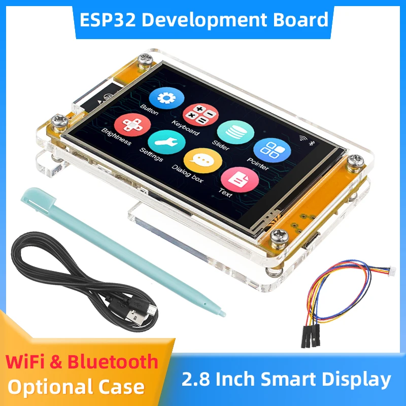
Identify your CYD before wiring
Read the PCB marking on the back, then match the LCD and touch controller to the board documentation. The table below is for the ESP32-2432S028R resistive-touch reference board. Compare your connector orientation and schematic before connecting an external device.
| Subsystem | Signal to GPIO | What to verify |
|---|---|---|
| LCD | SCK 14, MOSI 13, MISO 12, CS 15, DC 2, backlight 21 | LCD controller and backlight polarity |
| XPT2046 touch | CLK 25, MOSI 32, MISO 39, CS 33, IRQ 36 | Use the touch bus pins shown here |
| microSD | SCK 18, MOSI 23, MISO 19, CS 5 | Configure the SD bus independently of touch |
Start with an LCD-only test, then read raw touch coordinates, then mount a card. Verify exposed header signals before choosing pins for a sensor. 2.8-inch CYD setup · Touch troubleshooting · Reference board documentation
Before using the pin table
- Read the board silkscreen and match the revision to its schematic.
- Distinguish header labels from GPIO numbers and from library pin definitions.
- Check pins already assigned to onboard devices and boot functions before adding a sensor.
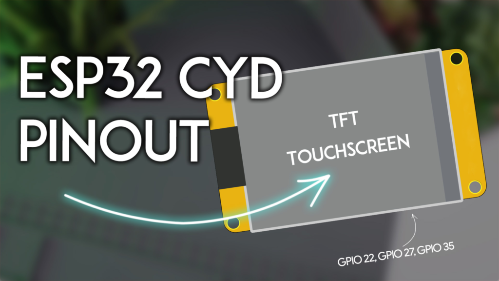
Complete Functional Pinout Breakdown
Display Interface (SPI - HSPI)
The LCD uses its documented SPI wiring. GPIO21 controls the backlight on the reference board; follow the board revision and TFT_eSPI configuration for the correct active level.
| SPI Function | GPIO Pin | Library Variable | Notes |
|---|---|---|---|
| MISO | GPIO 12 | TFT_MISO |
Master In, Slave Out |
| MOSI | GPIO 13 | TFT_MOSI |
Master Out, Slave In |
| SCLK | GPIO 14 | TFT_SCLK |
Serial Clock |
| Chip Select (CS) | GPIO 15 | TFT_CS |
Display enable pin |
| Data/Command (DC) | GPIO 2 | TFT_DC |
Differentiates data vs. command |
| Reset (RST) | -1 | TFT_RST |
Often tied to board's reset; use -1 |
| Backlight | GPIO 21 | TFT_BL |
Backlight control; match the active level to the board configuration |
Touchscreen Controller (SPI)
The resistive touchscreen uses the XPT2046 controller on the VSPI (SPI2) bus. For reliable touch functionality, ensure no other peripherals conflict with these pins.
| Touch Function | GPIO Pin | Common Variable |
|---|---|---|
| Interrupt (IRQ) | GPIO 36 | XPT2046_IRQ |
| MOSI | GPIO 32 | XPT2046_MOSI |
| MISO | GPIO 39 | XPT2046_MISO |
| Clock (CLK) | GPIO 25 | XPT2046_CLK |
| Chip Select (CS) | GPIO 33 | XPT2046_CS |
microSD Card Slot (SPI)
The microSD card shares the VSPI bus with the touchscreen but uses a separate Chip Select line. This allows both peripherals to coexist, though communication cannot happen simultaneously.
| SD Card Function | GPIO Pin |
|---|---|
| MISO | GPIO 19 |
| MOSI | GPIO 23 |
| SCK | GPIO 18 |
| Chip Select (CS) | GPIO 5 |
Integrated Peripherals & Indicators
-
RGB LED: This surface-mount LED is active-LOW (set pin LOW to turn ON).
-
Red: GPIO 4
-
Green: GPIO 16
-
Blue: GPIO 17
-
-
Light Dependent Resistor (LDR): Connected to GPIO 34 (an analog input-capable pin). Use
analogRead()to measure ambient light for auto-brightness features. -
Speaker Connector: The 2-pin JST port is driven by GPIO 26. Use PWM audio libraries or simple tone generation.
-
Buttons: BOOT is tied to GPIO 0. RST is connected to the ESP32's enable pin.
Maximizing Available GPIOs for Your Projects
This is the most critical section for project planning. While the ESP32 has many pins, the CYD's design pre-assigns most. Here is a realistic analysis of your free GPIOs.
"Extended IO" Connectors (P3 & CN1)
These headers provide primary access to free pins, but with important caveats.
P3 Connector Pins:
-
GPIO 35: A free, input-only pin. Excellent for reading sensors, buttons, or digital signals. It cannot be used as an output.
-
GPIO 22: A free, versatile GPIO. Crucially, this is one of the ESP32's default I2C SCL pins.
-
GPIO 21: NOT FREE. This pin controls the display backlight. It will be held in a fixed state while the display is on.
CN1 Connector Pins:
-
GPIO 27: A free, versatile GPIO.
-
GPIO 22: The same pin as on P3, available here for convenience.
-
3.3V & GND: Provide power to external sensors.
The I2C Solution: Creating a Custom Bus
You cannot use the default I2C pins (GPIO 21=SDA, GPIO 22=SCL) because GPIO 21 is occupied. The solution is to define a custom I2C bus using the free pins on CN1.
#include <Wire.h>
#define CUSTOM_SDA 27 // Use GPIO 27 on CN1
#define CUSTOM_SCL 22 // Use GPIO 22 on CN1/ P3

void setup() {
  Wire.begin(CUSTOM_SDA, CUSTOM_SCL); // Start I2C on custom pins
  // Now scan for I2C devices (sensors, RTC, etc.)
}
Project examples include environmental sensors and small control panels. Verify the external connector mapping and voltage requirements before connecting a peripheral.
Serial Ports: Use with Caution
The P1 connector provides GPIO 1 (TX) and GPIO 3 (RX). These are directly connected to the onboard CH340 USB-to-serial converter.
-
Primary Use: For connecting a secondary GPS module (like NEO-6M/8M). You must use a SoftwareSerial or HardwareSerial on different pins (e.g., GPIO 27 for RX, GPIO 22 for TX) to avoid conflict with USB communication.
-
Warning: As noted by many users, using P1 for other serial peripherals often interferes with programming and serial debugging. It is not generally recommended for beginner projects.
Final Tally: Truly Free GPIO Pins
After accounting for all integrated functions, you have three primary GPIOs for external components:
-
GPIO 35 (Input Only) – Read switches, analog sensors (via ADC), or digital inputs.
-
GPIO 22 (Input/Output) – Perfect for I2C SCL or general-purpose use.
-
GPIO 27 (Input/Output) – Ideal for I2C SDA, OneWire, or a simple output.
This configuration makes the CYD ideal for focused applications like sensor hubs with displays, IoT control panels, or smart clocks, rather than projects requiring dozens of outputs like large robotics.
Practical Configuration and Troubleshooting
Library and IDE Setup
-
Board Definition: In Arduino IDE or PlatformIO, select "ESP32 Dev Module."
-
TFT_eSPI Library: This is essential. After installing, navigate to its library folder and configure the
User_Setup.hfile. Select the correct driver (typicallyILI9341_DRIVER) and enter the pin definitions from the table above. Comment out unused drivers to save memory. -
Touch Calibration: Use the
TFT_eSPIexample "TouchCalibrate" to generate accurate calibration constants for your specific screen.
Common Issues and Solutions
-
"Failed to initialize SD card": Ensure the microSD card is formatted as FAT32 (not exFAT). Check that the
SD_CSpin (GPIO 5) is correctly defined. -
Intermittent touch or display glitches: compare the SPI configuration and power arrangement with the board guide. Use a reliable supply and data cable with the actual connector fitted to your revision.
-
Unable to Upload Code (CH340 Driver): On Windows, you may need to install the CH340 USB driver manually. Mac and Linux typically handle it automatically.
Project Ideas and Next Steps
Given its pin constraints, the CYD excels at these applications:
-
WiFi-Enabled Sensor Display: Connect a BME280 (via I2C on GPIO 22/27) and display real-time temperature/pressure/humidity graphs, posting data to MQTT.
-
Smart Home Control Panel: Use the touchscreen as an interface to control lights or relays via MQTT or HTTP. The RGB LED provides clear status feedback.
-
Internet Radio/Audio Player: Use the speaker output with an audio shield (connected via I2C) and the microSD for storing files.
Conclusion
The ESP32 Cheap Yellow Display strikes a remarkable balance between integrated convenience and programmability. While its available GPIOs are limited, strategic use of the CN1 connector for a custom I2C bus and understanding the role of each pin unlocks its true potential. By following this pinout guide, you can avoid common pitfalls and develop efficient, reliable projects that leverage its excellent touchscreen display as the centerpiece of your IoT innovation.
Ready to start coding? Begin with the basic TFT_eSPI examples to test your display and touchscreen, then integrate sensor libraries using the custom I2C pins outlined above. The community is active—share your creations and solutions to help the next maker
Contact Us
Related tutorials and hardware
- 2.8-inch CYD: ESP32-2432S028R
- CYD PlatformIO & LVGL workflow
- 2.8 Inch ESP32 CYD MCU Smart Display for Arduino LVGL WIFI Bluetooth Touch WROOM 240*320 Screen LCD TFT Module with Free Tutorials
Sources and version references
Related guide: Identify the CYD LCD driver before changing graphics configuration.
Choose the next step for this board
Use this page as the connector and GPIO reference. For the first display upload, continue with 2.8-inch CYD: ESP32-2432S028R. A white screen with a running sketch belongs in LCD driver identification; inaccurate input belongs in XPT2046 calibration sampling. Select the physical variant using the board comparison.