ESP32 Dev Board vs Custom PCB: When to Switch
Every ESP32 product starts on a dev board. That is the right way to start — you get a working

An ESP32 iot board design is a system problem wearing a PCB costume. It has to sense something, power itself, connect to a network, and hand data to firmware and cloud software that someone else is writing. If the board is designed in isolation from those realities, it works on the bench and fails in the field.
This guide covers what makes an esp32 iot device different from a general-purpose ESP32 board, and how to plan one that ships.
The most common IoT board mistake is starting with a component list. The better starting point is the data: what are you sensing, how often, how accurate, and where does it go?
Those answers determine almost everything:
Design the board around the data flow, not around a parts bin. A humidity sensor read once an hour and a vibration sensor sampled at kilohertz are the same ESP32 on paper and two completely different boards in practice.
ESP32 boards commonly use I2C, SPI, and analog inputs for sensors. Each has layout implications.
For precision sensing, the analog section deserves its own planning. A board that gets the RF right and the analog wrong is still a board that reports bad data. If your sensor output is a few millivolts, the switching regulator twenty millimeters away is your biggest enemy, and no amount of software filtering fully removes it.
IoT boards are often battery-powered or power-constrained, and the power design decides the product's viability.
A sensor node that sleeps at microamps and wakes briefly to transmit can run for years on a small cell — but only if the power architecture is designed for that, not bolted on. Do the arithmetic early: average current times 24 hours times 365 days, divided into your battery capacity. If the number is under your target, the design is viable; if not, no amount of firmware tuning will rescue it.
IoT products often live in enclosures that hurt RF: metal boxes, sealed plastic with coatings, or products mounted against walls. Plan the antenna with the enclosure and the installation in mind.
For esp32 iot solutions, "range" is often not about the chip at all — it is about the antenna, the enclosure, and the environment. A gateway in a metal cabinet and a sensor on a concrete wall will behave nothing like the two boards on your bench.
The board does not exist alone; it feeds firmware, which feeds cloud. Design the board so that handoff is clean.
A board with a clean firmware handoff saves weeks of integration debugging. The cost of a written pin map is an hour; the cost of an undocumented board is a team standing around a bench guessing which pad is the boot button.
For connected products, security starts on the board:
These are architecture decisions that must be made before layout, because they change the BOM and the routing. Adding a secure element after layout means a respin; deciding to disable the debug port after production means a firmware workaround that never quite holds.
The sensor choice and the bus choice are linked, and getting the pair wrong is a common source of rework.
Mixing buses is normal; a single product may use I2C for the environment and SPI for a display. The layout job is to keep the quiet buses quiet and the fast buses contained, which usually means routing them in separate regions rather than braiding them together.
Battery life claims are where IoT products most often disappoint, and the disappointment traces back to an estimate that used datasheet currents instead of the product's actual pattern.
Build the estimate from the profile:
Then apply the battery's usable capacity — not its nominal capacity, because voltage droop, temperature, and the regulator's efficiency all take a bite. A product advertised at five years that actually delivers two is usually the result of counting the sleep current but ignoring the regulator's quiescent draw, or assuming the battery holds its full capacity at the temperature the product will see.
An IoT product is deployed in numbers and lives in the field, often where you cannot easily reach it. That changes the design:
These are small decisions with outsized effects on the cost of owning a deployed fleet.
For a connected product, there is no clean line between "hardware design" and "security." The board has to make security possible:
Deciding any of these after layout means a respin, which is why they belong in the architecture phase, alongside the data-flow decisions.
For an IoT product, the enclosure is decided too late in most projects and it is the cause of too many surprises. Treat it as an input:
A board designed without the enclosure in view tends to fit the enclosure badly and perform worse inside it. Bringing a mechanical drawing into the design review costs nothing and prevents a category of problem that is otherwise discovered after tooling.
An IoT product is deployed, not just built, and the deployment shapes the requirements:
A board that is designed for a fleet, not for a single prototype, is a board that avoids a long list of second-order problems that only appear at scale. The same iot hardware design discipline that serves a single device serves a fleet.
The firmware team is a stakeholder in the board design, and their requirements are concrete:
A board designed without those answers forces the firmware team to work around the hardware, which is slower and produces worse products. Bringing the firmware lead into the design review, even for an hour, catches misunderstandings while they are still drawings.
There is a mirror image of the cost-cutting mistake: building an IoT board that is far more capable than the product needs. Extra sensors, extra radios, extra memory, and extra connectors all add cost, board area, power draw, and failure modes.
The discipline is to design for the product's actual requirements and to leave room for one revision, not for every feature anyone might want. The features that matter will reveal themselves once the product is in customers' hands, and it is cheaper to add them deliberately than to carry them speculatively.
Occasionally an IoT product is better served not by a bare module but by a system-on-module that includes memory, storage, and sometimes power management. The trade-offs are similar to the module-versus-chip-down decision: a more integrated part is faster to bring up and easier to certify, but it costs more and offers less freedom.
For a product with tight time-to-market and modest volume, the integrated route often wins; for a cost-sensitive product at volume, the bare module or chip-down route usually does.
A final point on the IoT board: keep the first version simple. An IoT product that ships with a minimal, well-understood board is easier to debug, cheaper to certify, and faster to improve than one that ships with every feature enabled. The features that customers actually want will become obvious after launch, and it is cheaper to add them deliberately than to carry them speculatively from the start.
If there is one habit that most improves an IoT board, it is writing the pin map down before layout and keeping it current. Firmware, test, and the enclosure all depend on it, and a board whose pin map lives only in the designer's head is a board that will be mis-wired at least once.
A final IoT habit: keep a written record of every design decision that a future engineer would not be able to reconstruct — the antenna choice, the power architecture, the security hardware. On a product that will be revised and serviced for years, that record is the difference between a design that can be maintained and one that has to be rebuilt.
And a last IoT reminder: the board is only half the product. The other half is the firmware, the cloud, and the deployment, and the board has to make all three possible. Design for the system, and the system will thank you.
We design esp32 iot board designs with the sensor, power, RF, and firmware handoff planned together, so the board does not surprise the software team. If that is the kind of product you are building: pcb-design for the full path, pcb-layout if you already have the schematic.
Manufacturing and assembly run through PCB PCBA order online.
Send us your data requirements and enclosure, and we will help you scope the board.
An ESP32 IoT board is a system, not just a PCB. Start from the data flow — sample rate, accuracy, volume, and connectivity pattern — before choosing parts. Plan the sensor interfaces, especially analog, away from noise. Build the power architecture from the duty cycle, not the datasheet. Choose the antenna for the real enclosure and mounting position. Bring out debug and test access, document the pin map, and plan the firmware and cloud handoff.
Security hardware decisions must be made before layout, because they change the BOM.
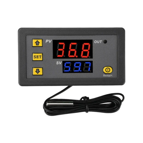 W3230 12V 24V AC110-220V Probe line 20A Digital Temperature Control LED Display Thermostat With Heat/Cooling Control Instrument
$4.90
W3230 12V 24V AC110-220V Probe line 20A Digital Temperature Control LED Display Thermostat With Heat/Cooling Control Instrument
$4.90
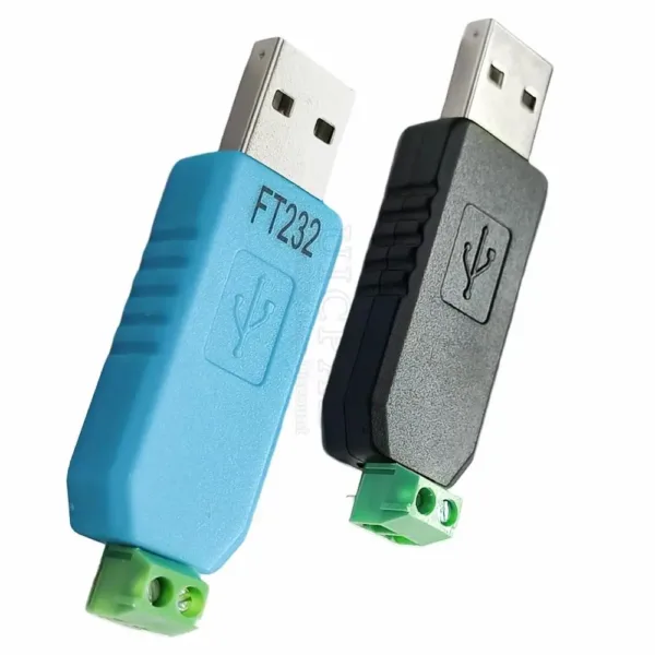 USB CH340 to RS485 Convertor Module PL2303 to 485 FT232 to RS485 USB Tool Conversion Adapter for Win 7 8 XP
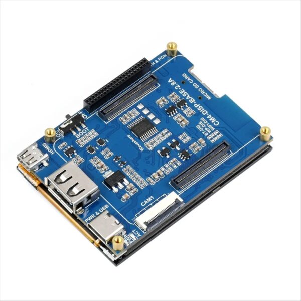 Dynamic CM4 Expansion Board 2.8inch Touch Screen Display HAT USB HUB Starter Kit for RPI Raspberry Pi Compute Module 4 Lite EMMC
$66.90
Dynamic CM4 Expansion Board 2.8inch Touch Screen Display HAT USB HUB Starter Kit for RPI Raspberry Pi Compute Module 4 Lite EMMC
$66.90
 ESP32 WIFI Bluetooth Development Board with 0.96-inch OLED Display 18650 Li-Ion Battery Pack for IoT Smart Home Systems
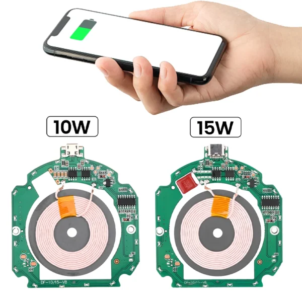 10-15W wireless charging PCBA motherboard transmitter module wireless charger 5V9V12V DIY RV Wireless Charger pcba
$3.60 – $4.60Price range: $3.60 through $4.60
10-15W wireless charging PCBA motherboard transmitter module wireless charger 5V9V12V DIY RV Wireless Charger pcba
$3.60 – $4.60Price range: $3.60 through $4.60
Every ESP32 product starts on a dev board. That is the right way to start — you get a working
Everyone talks about PCB layout, but the schematic is where most of the expensive mistakes actually happen. A layout error
esp32 pcb certification is one of the few parts of hardware development where the cost of getting it wrong is
The ESP32-WROOM is probably the most common ESP32 module in the world. It is cheap, well-documented, and appears in thousands
The ESP32-S3 is the part people reach for when their product needs more than the classic ESP32 can give: native
Designing an ESP32 board and assembling it are two different disciplines, and the gap between them is where a lot
No account yet?
Create an Account