ESP32-S3 PCB Design: Camera, USB, and AI Workloads
The ESP32-S3 is the part people reach for when their product needs more than the classic ESP32 can give: native

The ESP32-WROOM is probably the most common ESP32 module in the world. It is cheap, well-documented, and appears in thousands of products. It is also, in our experience, one of the most frequently mis-laid-out parts — because people treat it as a component to be placed wherever it fits, rather than as a radio that needs specific conditions around it.
This article is about getting the esp32 wroom pcb layout right: where to place it, what keep-out it needs, and how to ground it. Most of what follows applies whether you are designing an esp32 wroom 32 pcb or using one of the newer WROOM variants, because the physics of the antenna does not change with the part number.
The WROOM integrates the ESP32 chip, flash, the crystal, and the RF matching network, and it presents an antenna at one end. That antenna is the part that matters. Everything else in the module is taken care of; the antenna's environment is not.
Two versions matter here:
Which one you have determines the keep-out you must respect.
For a WROOM with a PCB antenna, the antenna is at one end of the module, and the module datasheet specifies a keep-out region: an area where you must not place copper, traces, or components.
The rules, in practice:
The most common failure is a ground pour that was drawn before the module was placed, extending quietly into the antenna region. It looks fine on screen and kills the range in the field. If your EDA tool supports a copper keep-out rule, set it up once and let it protect you through every reroute.
The single most important placement rule is to put the antenna at the edge of the board, facing outward. A module buried in the middle of the board radiates into its own ground plane and enclosure, and the range suffers.
Practical guidance:
If your mechanical design puts the antenna against a metal surface, no amount of layout skill will fix it. That is an enclosure conversation, and it is better to have it before the enclosure is tooled. A common cheap fix is to leave a plastic window in a metal enclosure directly over the antenna, or to switch to the external-antenna module.
The WROOM needs a solid ground reference. The rules:
A module whose ground pads are connected by thin, sparse traces will underperform a properly grounded one, even with identical placement. If in doubt, count the vias around the module's ground pads and compare that number to the number of ground pads; a ratio well below one-to-one is a red flag.
The WROOM has its own decoupling, but the board still has to supply clean power.
The transmit burst of an ESP32 is what stresses the supply, not the average current. If the 3.3 V rail sags during transmission, you get resets or dropped packets that look like software bugs and are actually layout bugs. A scope on the rail, triggered on transmit, tells you in seconds whether the supply is the problem.
The "U" version moves the antenna off the module, which changes the layout:
External antennas are the right answer for products where the enclosure is metal or the range requirement is high. They also let you position the antenna away from noisy circuitry, which is often the single biggest range improvement available to a small product.
The keep-out is not a suggestion; it is a dimension with a tolerance, and it appears in the module's hardware design documentation. When you read it:
The single most common datasheet misread is treating the keep-out as covering only the top layer, then filling the bottom layer with ground under the antenna. The copper is on the wrong side of the board, and it still detunes the antenna.
Small ESP32 products are where the antenna rules get tested hardest, and the physics does not negotiate. When the board is too small, three things happen:
The result is a board that passes a bench test at short range and fails in the field at realistic distance. The fix is usually not a layout trick but a product decision: a slightly larger board, a module with an external antenna connector, or an antenna designed into the product's plastic.
You cannot see an antenna problem on a schematic, and you often cannot see it on a layout review. The only reliable test is measurement. Two accessible methods:
A product that has had neither test has an antenna that is assumed to work rather than known to work, and the difference shows up as a support problem after shipping.
It is worth being blunt about the economics. A layout that gets the antenna wrong produces one of the most expensive failure modes in hardware: the product works in the lab, passes basic functional testing, ships, and then fails in the field in a way that is intermittent and hard to attribute. Fixing it means a respin, a re-test, and often a re-certification, plus the cost of the returns and the reputation.
Against that, the cost of getting it right is a keep-out rule, an edge placement, and a measured antenna. There is no cheaper insurance in hardware design.
Two WROOM boards can place the module identically and perform differently, and the difference is usually the ground. The module's ground pads need a low-impedance path to the board's ground plane, and that path is made of vias and copper:
The rule of thumb is that if a ground connection looks like a single bottleneck, it is one. The antenna and the radio care about the impedance of their return path, and a thin ground link is a resistor you did not intend to add.
Before committing to a production run, a short test programme catches the most expensive mistakes:
None of these require a full test lab, and together they cover the failure modes that a WROOM layout can have despite looking correct on screen.
A metal enclosure is the hardest environment for a WROOM with a printed antenna, and it is common in industrial and outdoor products. Options, in order of increasing effort:
What does not work is putting a printed antenna facing a solid metal wall and expecting range. The antenna will be detuned and shielded, and the product will underperform no matter how good the layout is. This is why the enclosure belongs in the design conversation from the start.
The antenna has the strongest claim on placement, but it is not the only consideration. Once the module is placed at the edge with its keep-out respected, the rest of the board has to work around the constraints it creates:
Laying the board out around the module — rather than squeezing the module into a board that was laid out for something else — is the difference between a WROOM design that works and one that only appears to.
It is worth remembering why the WROOM remains so common despite newer parts. It is cheap, it is available in volume, it is documented to a fault, and its integration is well understood by contract manufacturers. For a product that needs reliable Wi-Fi, a proven module, and a fast path to production, the WROOM is often the lowest-risk choice. The layout discipline it demands is the price of that reliability, and it is a price worth paying deliberately.
If the WROOM is going into a product that will be mounted in different orientations, test the antenna in the worst one, not the best. A device that works lying flat and fails when mounted vertically has an antenna problem that a bench test in the wrong position will hide. Test as the customer will install it.
Finally: if the WROOM board passes range testing in the lab but disappoints in the field, suspect the enclosure and the mounting before the layout. The module is usually doing exactly what it was designed to do; the environment around it is what changed.
We lay out WROOM-based boards constantly, and getting the antenna right is routine work for us. If your product uses a WROOM and the range matters: pcb-layout. For full design from schematic to Gerbers, see pcb-design. Manufacturing and assembly run through PCB PCBA order online.
Send us your board outline and enclosure constraints, and we will tell you where the WROOM should go.
The ESP32-WROOM's antenna is easy to ruin. Place the module at the board edge with the antenna facing outward, and keep the keep-out clear of copper, components, and ground pour on every layer. No metal — battery, screws, or enclosure — should sit near the antenna. Keep a continuous, well-stitched ground under the module body, keep switching supplies away, and test the antenna in the real enclosure.
If your enclosure is metal or your range requirement is high, use the external-antenna version instead.
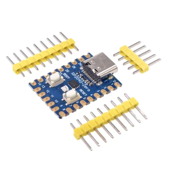 RP2040-Zero RP2040 for Raspberry Pi Microcontroller PICO Development Board Module Dual-core Cortex M0+ Processor 2MB Flash
$3.20 – $3.50Price range: $3.20 through $3.50
RP2040-Zero RP2040 for Raspberry Pi Microcontroller PICO Development Board Module Dual-core Cortex M0+ Processor 2MB Flash
$3.20 – $3.50Price range: $3.20 through $3.50
 LILYGO T-RGB ESP32-S3 2.1 inch Round Display ST7701S LCD Touch Screen ESP32-S3R8 Development Board Support WIFI Bluetooth TF
$42.90
LILYGO T-RGB ESP32-S3 2.1 inch Round Display ST7701S LCD Touch Screen ESP32-S3R8 Development Board Support WIFI Bluetooth TF
$42.90
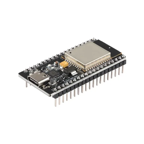 ESP32 WROOM-32 Development Board TYPE-C CH340C/ CP2102 WiFi+Bluetooth Ultra-Low Power Consumption Dual Core Wireless Module
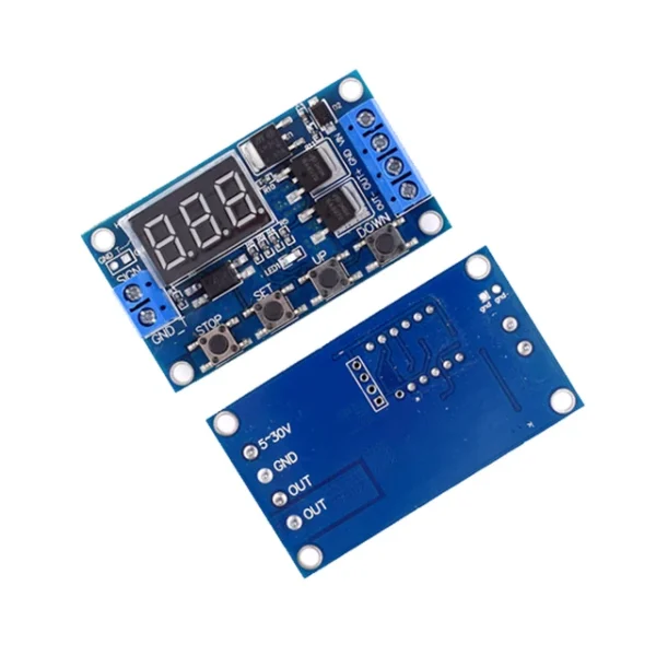 Trigger Cycle Timing Delay Switch Circuit Dual MOS Tube Control Board Instead Of Relay Module
$2.90
Trigger Cycle Timing Delay Switch Circuit Dual MOS Tube Control Board Instead Of Relay Module
$2.90
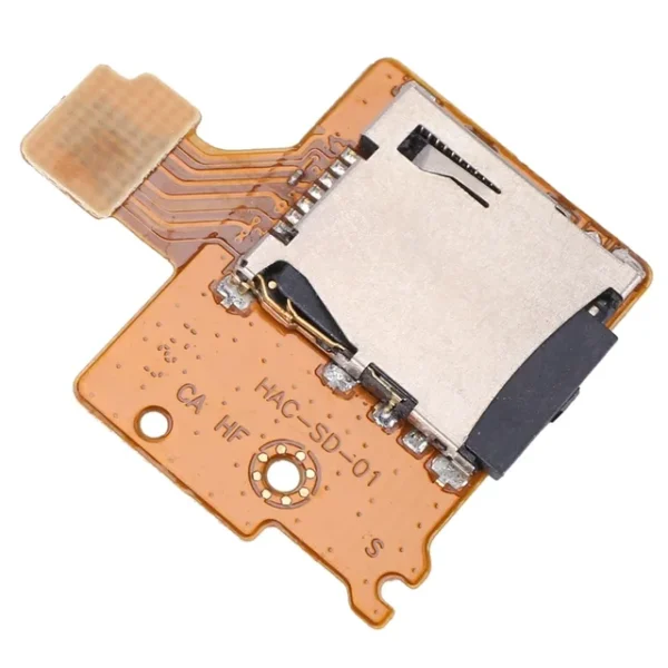 SD Card Reader for Nintend Switch Game Console SD Card Board Module Replacement SD TF Card Slot Socket Board
$2.30
SD Card Reader for Nintend Switch Game Console SD Card Board Module Replacement SD TF Card Slot Socket Board
$2.30
The ESP32-S3 is the part people reach for when their product needs more than the classic ESP32 can give: native
Designing an ESP32 board and assembling it are two different disciplines, and the gap between them is where a lot
Once your ESP32 design is done, the next decision is who builds it. This is where a lot of teams
If you want to sell a connected product but do not want to build a hardware team, the words "OEM"
EMC testing is expensive, and failing it is worse than the test fee — it costs you a respin, a
We review a lot of boards — some designed in-house, some by other contractors, some by founders doing their own
No account yet?
Create an Account