ESP32-WROOM Layout: Antenna, Keep-Out, and Module Placement
The ESP32-WROOM is probably the most common ESP32 module in the world. It is cheap, well-documented, and appears in thousands

The ESP32-S3 is the part people reach for when their product needs more than the classic ESP32 can give: native USB, more memory, more GPIO, and vector instructions that make it usable for on-device AI and camera work. Those extra capabilities are real, and they change what the layout has to handle.
If you are porting a classic ESP32 design to the S3, or starting fresh, here is what actually differs. The esp32-s3 pcb itself is not harder than a classic ESP32 board — but it asks more of your layout discipline, because every new interface is a new opportunity to break a return path.
The S3 is still a 2.4 GHz Wi-Fi and BLE part, so the antenna rules you already know still apply. What changes is everything around the radio:
Each of these brings layout consequences the classic ESP32 did not have. The esp32 s3 hardware design guidelines from Espressif cover the pinout and the peripheral list; what they do not do is make the layout decisions for you, which is where this article helps.
The S3's native USB is the biggest change for many designs. Unlike a USB-to-UART bridge, the native USB is routed directly from the chip, and it must be laid out as a proper differential pair.
The most common mistake is routing USB as two casual GPIO traces because "it worked on the dev board." It often does work at low speed — until it does not, usually at temperature or on some units. If you are adding an external antenna to your S3 and routing the coax or feed near the USB pair, keep the two apart; a noisy USB pair next to an antenna feed is a reliable way to lose sensitivity.
If you use the S3's camera interface, you are routing a parallel bus — data lines, pixel clock, and sync signals — and the timing has to hold. That means:
Camera layouts fail in ways that are hard to debug — an image that is fine in the lab but tears under load. Length and return-path discipline is what prevents it. If the camera connector must sit far from the module, consider terminating the clock and keeping the data group as short as the mechanical constraints allow; a few millimeters of extra length on the pixel clock group is usually fine, but a broken ground under it is not.
The S3 is still 2.4 GHz, so the keep-out, feedline, and grounding rules are the same as any ESP32. But because the S3 boards are often denser (camera, USB, more memory), it is easier to violate the keep-out accidentally.
If you go chip-down with an S3, the RF and certificate work is yours. A pre-certified S3 module transfers most of it, but only if you follow the module's integration rules. For a camera product, the module route usually wins on schedule; a chip-down esp32 s3 external antenna design is justified mainly when the enclosure leaves no room for the module's printed antenna and you need a connector instead.
The S3 draws more current than older parts when the radio, USB, and camera are active, and it has more supply pins to decouple.
A useful check: add up the camera's peak current, the Wi-Fi transmit burst, and the USB current if all three can occur at once. If your regulator is sized on the datasheet's average, it will brown out exactly when the product is doing its most visible work.
The S3 typically uses an external crystal for the main clock, and the rules are the same as other ESP32 parts: place it close, keep load capacitors close, guard it with ground, and follow the reference layout. Do not improvise.
A camera on an ESP32-S3 is not just a data problem; it is an electromagnetic one. The camera's clock and data lines switch fast, and their harmonics can land inside the 2.4 GHz band, where they raise the noise floor under your own radio. The symptom is subtle: the camera works, the Wi-Fi works, but the effective range drops when the camera is streaming.
Practical mitigations:
This is the sort of problem that a schematically perfect design can still have, because it lives in the layout and in the interaction between two subsystems that each work alone.
The S3 boards that carry a camera, USB, and a fast radio get warm, and warmth has two consequences: it shifts the crystal (nudging timing) and it raises leakage and current draw (hurting battery life and stability). On a dense board, plan for it:
A board that behaves on the bench in open air can misbehave inside a sealed product, and thermal layout is part of preventing that.
When the first S3 boards come back, the order in which you test them saves time:
Testing in this order means that when something fails, you know it failed in isolation, not as a side effect of three other subsystems.
For a product with a USB-C port, the connector is where electrical and mechanical design meet, and it is a frequent source of field returns. A few points that pay off:
The USB port is the interface most likely to be touched by a user, and it should be designed for that reality rather than as an afterthought at the board edge.
On an S3 board that has both a camera and a radio, one of them has to be the anchor of the layout, and the other arranged around it. For most products the antenna should win, because the antenna's needs are less negotiable: it needs the board edge and it needs clear space, while the camera can often be routed with longer, carefully controlled traces.
Deciding early which subsystem is the anchor prevents the classic outcome where the antenna is squeezed into a corner after everything else has claimed the good space. Place the radio first, place the camera second, and route the support circuitry around both.
The S3's vector instructions make light AI possible on the device, but they do not add a special layout requirement of their own. What they change is the consequence of doing that work locally:
So the AI capability is, from a layout perspective, mostly an amplifier of the requirements the camera and the radio already impose. The board still rests on the same fundamentals: return paths, decoupling, and keeping the noisy subsystems away from the sensitive ones.
Because an S3 board with a camera and USB has more moving parts than a simple ESP32 board, the schedule is longer, and planning it realistically avoids disappointment:
Rushing the layout of this class of board is the most common way to spend the time twice, because a return-path error on a camera bus can force a respin.
An S3 board with a camera and USB is a genuine step up in layout difficulty, but it is not mysterious. Every additional interface adds the same two requirements: keep the return path continuous, and keep the noisy parts away from the quiet ones. A designer who holds those two rules through the whole board will get a design that works; one who treats each interface in isolation will get a design that works on the bench and surprises them in the field.
One more item for the porting checklist: confirm the module's antenna version. An S3 module with a printed antenna and one with a connector have different keep-outs, and porting a design without checking which one you have is a reliable way to discover the difference after fabrication. Read the module's part number against its datasheet before the layout is frozen.
The last item on the porting checklist deserves repeating: verify the antenna version of your module before layout. A printed-antenna module and a connector module have different keep-outs, and the difference is invisible until the board is built. A minute with the datasheet prevents a respin.
We lay out ESP32-S3 boards, including camera and USB designs where the interface layout decides whether the product works. If you need the esp32 s3 pcb done right the first time, that is our layout service. For the full path from schematic to Gerbers, see pcb-design.
Manufacturing and assembly run through PCB PCBA order online.
Send us your S3 design and we will flag the USB, camera, and RF risks before layout.
The ESP32-S3 adds native USB, more memory, and vector instructions for camera and AI work — and each changes the layout. Native USB must be a controlled 90 ohm differential pair, not two casual traces. The camera interface is a timing-critical parallel bus that needs length control and a clean return path. The antenna rules are unchanged but easier to violate on a denser board. Power and decoupling must cover the S3's higher peak current.
Re-derive the layout from the S3 reference rather than porting a classic ESP32 board, and decide module versus chip-down early.
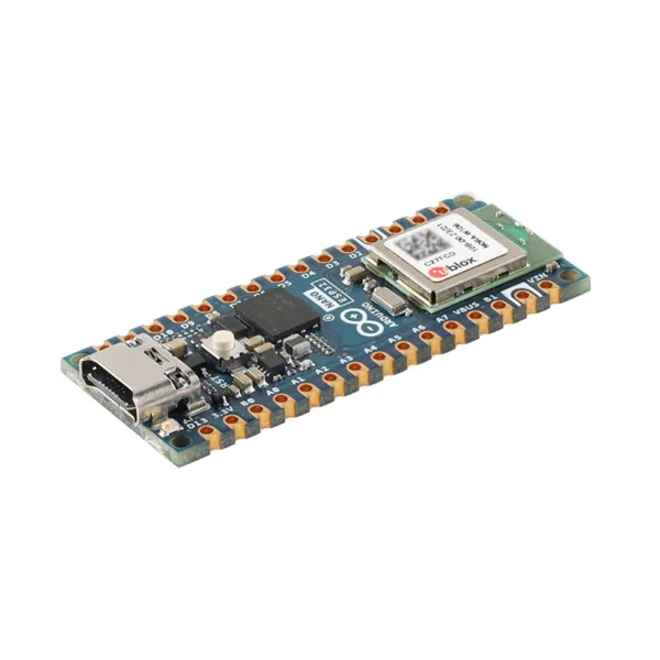 ARDUINO NANO ESP32 ABX00092 u-blox NORA-W106 (ESP32-S3) development board
 Radxa Camera 8M 219, Supports Radxa SBCs, IMX219 Sensor
$26.90
Radxa Camera 8M 219, Supports Radxa SBCs, IMX219 Sensor
$26.90
 BME68X Environmental Sensor for Raspberry Pi/Jetson Nano/Audio/ESP32, Temperature, Humidity, Barometric Pressure
$15.90 – $26.70Price range: $15.90 through $26.70
BME68X Environmental Sensor for Raspberry Pi/Jetson Nano/Audio/ESP32, Temperature, Humidity, Barometric Pressure
$15.90 – $26.70Price range: $15.90 through $26.70
 Bluetooth Gateway Hub Smart Home Bridge Support Fingerbot Tuya Bluetooth Device Smart Life App Remote Control Mesh Bridge
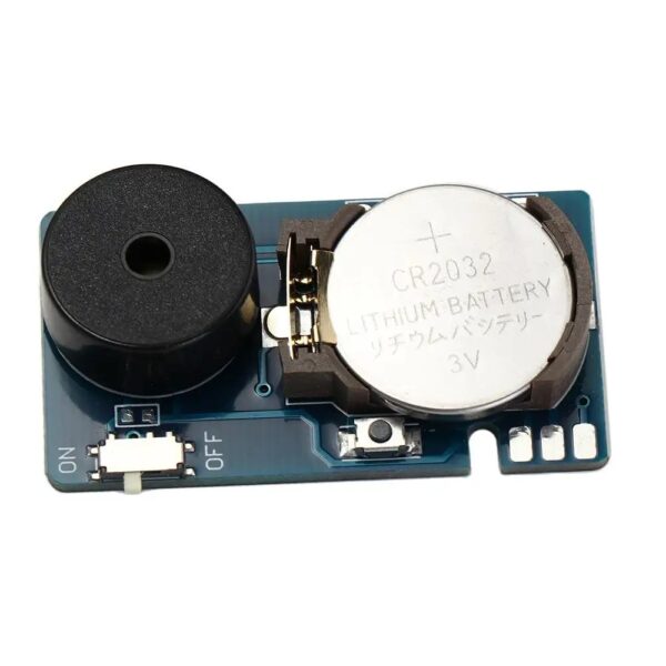 Prank Noise Maker Annoying Noise Maker Beeper Prank Device PCB Beeping Prank
$3.50
Prank Noise Maker Annoying Noise Maker Beeper Prank Device PCB Beeping Prank
$3.50
The ESP32-WROOM is probably the most common ESP32 module in the world. It is cheap, well-documented, and appears in thousands
Designing an ESP32 board and assembling it are two different disciplines, and the gap between them is where a lot
Once your ESP32 design is done, the next decision is who builds it. This is where a lot of teams
If you want to sell a connected product but do not want to build a hardware team, the words "OEM"
EMC testing is expensive, and failing it is worse than the test fee — it costs you a respin, a
We review a lot of boards — some designed in-house, some by other contractors, some by founders doing their own
No account yet?
Create an Account