Why the PCB Substrate Dictates Product Reliability
In electronics design, the PCB substrate is often treated as a commodity—a simple "green board" to hold components. This is a critical misconception. The substrate is a highly engineered composite of resin (binder) and reinforcement (e.g., woven fiberglass), and its physical and electrical properties form the absolute ceiling of your product’s performance.
Whether you are designing a cost-sensitive consumer IoT device, a high-frequency 5G telecommunications module, or an under-hood automotive control unit, the substrate must withstand mechanical stress, thermal cycling, and environmental factors while maintaining strict electrical parameters.
Choosing the wrong substrate to save a few cents per unit can lead to catastrophic field failures, costly respins, and damaged brand reputation. Understanding the nuanced trade-offs between different substrate materials is a mandatory discipline for any hardware team aiming for high-yield, scalable manufacturing.
Deep Dive: Core PCB Substrate Materials and Their Engineering Applications
Not all substrates are created equal. Selecting the right material requires balancing electrical performance, thermal requirements, mechanical rigidity, and budget.
1. Standard and High-Tg FR-4 (The Industry Workhorse)
- Composition: Woven fiberglass cloth impregnated with epoxy resin.
- Best For: General consumer electronics, industrial controllers, and standard computing devices.
- The Engineering Reality: Standard FR-4 has a Glass Transition Temperature (Tg) of around 130°C–150°C. For products undergoing multiple lead-free reflow cycles (peaking at ~260°C) or operating in high-ambient-temperature environments, High-Tg FR-4 (Tg ≥ 170°C) is mandatory. It prevents the resin from softening, which mitigates Z-axis expansion and protects plated through-holes (PTH) from barrel cracking.
2. High-Frequency / High-Speed Substrates (Rogers, PTFE, PPO)
- Composition: Specialized ceramic-filled hydrocarbons, Polytetrafluoroethylene (PTFE), or Polyphenylene Oxide (PPO).
- Best For: 5G/6G antennas, mmWave radar, aerospace telemetry, and high-speed digital backplanes (112G+ SerDes).
- The Engineering Reality: Standard FR-4 suffers from high signal loss (attenuation) and inconsistent Dielectric Constant (Dk) at frequencies above 2 GHz. Materials like Rogers RO4000 series offer a stable, low Dk and an ultra-low Dissipation Factor (Df), ensuring precise impedance control and minimal signal degradation.
3. Metal Core Substrates (MCPCB: Aluminum or Copper)
- Composition: A metal base (usually aluminum for cost/weight balance, or copper for maximum thermal conductivity) topped with a dielectric layer and a thin copper circuit layer.
- Best For: High-power LED lighting, automotive headlamps, power supply modules, and motor controllers.
- The Engineering Reality: FR-4 is a thermal insulator. In high-power applications, heat trapped at the component level causes premature failure. Aluminum MCPCBs can dissipate heat 5x to 10x more efficiently than standard FR-4, drawing thermal energy away from sensitive components and into the chassis or heatsink.
4. Polyimide (PI) and Flexible Substrates
- Composition: High-performance polymer films.
- Best For: Wearables, medical implants, and applications requiring dynamic flexing or 3D packaging.
- The Engineering Reality: While offering extreme flexibility and high-temperature resistance (Tg > 250°C), PI substrates are highly susceptible to moisture absorption. They require strict baking protocols before lamination and assembly to prevent the "popcorn effect" (delamination due to trapped moisture turning to steam).
Top 3 Substrate-Related Manufacturing Pain Points (And How We Solve Them)
As a hardware developer or supply chain manager, your goal is to maximize first-pass yield. Here are the most common substrate-related failures and how a professional manufacturing partner mitigates them:
1. Thermal Delamination and Via Cracking
The Pain Point: During thermal cycling, the substrate expands. If the Z-axis Coefficient of Thermal Expansion (CTE) is too high, it pulls on the copper plating inside the vias. Over time, or during aggressive reflow soldering, this causes the via barrel to crack, resulting in intermittent or total electrical failure.
Our Solution: We proactively recommend High-Tg and Low-CTE materials for demanding applications. Furthermore, our CAM engineers optimize the drilling and plating parameters to ensure robust copper deposition, and we enforce strict pre-baking procedures to eliminate moisture before lamination.
2. Impedance Mismatch and Signal Loss
The Pain Point: A designer specifies a 50Ω single-ended trace on a standard FR-4 board for a high-frequency RF application. Due to the inconsistent Dk of FR-4 at high frequencies and variations in resin content, the actual impedance measures 55Ω+, causing signal reflection and data corruption.
Our Solution: For high-speed designs, we utilize advanced field solvers to calculate the exact stack-up. We source certified low-loss materials (e.g., Isola, Rogers) and guarantee impedance tolerance within ±10%, backed by Time Domain Reflectometry (TDR) testing reports on every production panel.
3. Substrate Warpage During Assembly
The Pain Point: Asymmetric copper distribution or the use of thin, low-Tg substrates can cause the bare board to warp when exposed to the heat of the SMT reflow oven. This leads to misaligned components, solder bridging, or "open" joints.
Our Solution: Our DFM (Design for Manufacturability) team analyzes your copper balance. If necessary, we add "thieving" copper (dummy patterns) to balance the thermal mass across the board. For assembly, we customize the reflow thermal profile specifically to match the Tg and thermal mass of your chosen substrate, ensuring a flat, defect-free board.
Decision Matrix: Choosing the Right Substrate for Your Project
Expert Insight: You do not always need to build an entire board out of expensive high-frequency material. We frequently design and manufacture hybrid stack-ups (e.g., bonding a thin Rogers layer to a thicker FR-4 core). This places the expensive material only where the RF signals travel, while using cost-effective FR-4 for the rest of the board, optimizing both performance and BOM cost.
Why Partner with a Professional PCB Substrate & Assembly Manufacturer?
Sourcing a PCB substrate is not a commodity purchase; it is a strategic supply chain decision. The manufacturer you choose must possess the technical expertise to handle diverse materials without compromising yield, schedule, or electrical performance.
We bridge the gap between theoretical design and high-reliability manufacturing reality. Our end-to-end capabilities ensure your project succeeds at every stage:
- Expert Material Consultation & DFM: Before you finalize your design, our engineering team reviews your requirements. We help you select the optimal substrate based on your thermal, electrical, and budget constraints, preventing costly over-engineering or under-specifying.
- Seamless Prototyping to Turnkey Assembly: The substrate you choose directly impacts how the board must be assembled. We offer rapid-turn PCB prototyping coupled with complete turnkey PCB assembly manufacturing. Whether your design requires specialized reflow profiles for High-Tg materials or precise thermal management for MCPCBs, we manage the entire BOM, source authentic components, and deliver fully tested units. Explore our integrated workflow: PCB Prototype & Turnkey PCB Assembly Manufacturing.
- Scalable OEM/ODM Bulk Production: When your design is validated, scaling up requires industrial-grade quality control. We adhere to strict IPC-6012 Class 2 and Class 3 standards, utilizing Automated Optical Inspection (AOI), X-ray inspection, and comprehensive electrical testing. We guarantee consistent quality, material traceability, and competitive pricing for high-volume runs. Request a detailed quote for your next large-scale project: OEM/ODM Bulk Inquiry.
Frequently Asked Questions (FAQ)
Q1: Can I mix different substrate materials in a single multilayer PCB?
A: Yes. This is known as a "hybrid" or "mixed-material" stack-up. It is a highly effective cost-saving strategy for RF designs, where a thin layer of high-frequency material (like Rogers) is laminated onto a thicker, cost-effective FR-4 core. Our engineering team can design and manufacture these complex stack-ups reliably.
Q2: How do I know if my design requires High-Tg FR-4 instead of standard FR-4?
A: If your product will undergo lead-free SMT assembly (which requires peak temperatures of ~260°C), will be exposed to operating environments above 80°C, or requires multiple reflow cycles (e.g., double-sided SMT), High-Tg FR-4 (Tg ≥ 170°C) is strongly recommended to prevent delamination and warpage.
Q3: What is the difference between Dk and Df in PCB substrates?
A: Dk (Dielectric Constant) determines the speed of the electrical signal and is critical for calculating trace impedance. Df (Dissipation Factor) measures the amount of signal energy lost as heat as it travels through the material. For high-frequency applications, you need a substrate with both a stable Dk and a very low Df.
Q4: Do you provide material certification for regulated industries?
A: Absolutely. For medical, automotive, and aerospace applications, we provide full material traceability, including UL certifications, RoHS/REACH compliance documentation, and Certificates of Conformance (CoC) for all substrate materials used in your production run.
Build Your Product on the Right Foundation
The PCB substrate is the unsung hero of your electronic device. It dictates the thermal limits, signal integrity, and mechanical lifespan of your product. Compromising on material selection or partnering with a manufacturer who lacks the expertise to process advanced substrates is a direct risk to your product’s reliability and time-to-market.
Don’t leave your product’s foundation to chance. Whether you need a cost-optimized FR-4 design for a consumer gadget, a hybrid stack-up for a 5G module, or a thermally robust Aluminum MCPCB, we have the engineering expertise, advanced equipment, and quality management systems to deliver.

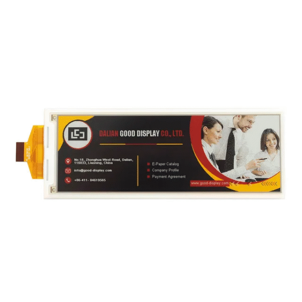 5.79 Inch Four-Color E-Ink Long Strip Screen 792x272 E-Paper Display
$21.90 – $42.90Price range: $21.90 through $42.90
5.79 Inch Four-Color E-Ink Long Strip Screen 792x272 E-Paper Display
$21.90 – $42.90Price range: $21.90 through $42.90
 UN-ESP32 C3 1.69 Inch LCD Touch Screen 240X280 Mini TV LVGL Astronaut Clock Watch Screen With Battery Compartment
$24.90
UN-ESP32 C3 1.69 Inch LCD Touch Screen 240X280 Mini TV LVGL Astronaut Clock Watch Screen With Battery Compartment
$24.90
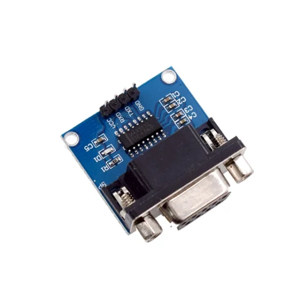 MAX3232 RS232 to TTL Serial Port Converter Module DB9 Connector MAX232 For Arduino
$2.20
MAX3232 RS232 to TTL Serial Port Converter Module DB9 Connector MAX232 For Arduino
$2.20
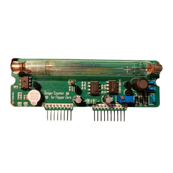 For Flipper Zero Multiboard Expansion Board Geiger Counter Module Kit Assembled Radiation System DIY Miller Tube
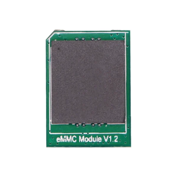 Radxa eMMC Module, Up to 128GB, Compatible with Radxa SBCs, Pluggable, High Quality Storage Chips
$18.90 – $103.90Price range: $18.90 through $103.90
Radxa eMMC Module, Up to 128GB, Compatible with Radxa SBCs, Pluggable, High Quality Storage Chips
$18.90 – $103.90Price range: $18.90 through $103.90