
EMC/EMI Checklist Before Your Board Goes to Certification
EMC testing is expensive, and failing it is worse than the test fee — it costs you a respin, a
When a battery-powered product dies too soon, the instinct is to blame the firmware. Surely there is a sleep mode that was not entered, a peripheral that was not disabled, a timer that kept waking the MCU. Sometimes that is true. But very often the firmware is perfect and the product still drains fast — because the board itself is consuming current the firmware cannot see.
A battery-powered design is not just an electronic design with a battery attached. It is a design where the quiescent behavior of every component on the board matters as much as the active behavior. And that is decided largely in the layout and the component selection, before firmware runs at all.
Datasheets love to headline peak current. For a battery product, peak current is rarely the problem — it is high for only microseconds or milliseconds at a time. The number that decides battery life is the average current, and in a product that sleeps 99% of the time, the average is dominated by the sleep current.
This reframes the whole design. You are not trying to reduce the transmit current; you are trying to reduce the current the board draws when it is doing nothing. That is a layout-and-selection problem.
If your product runs from a lithium cell through a regulator to 3.3 V, that regulator's quiescent current may be the single largest sleep-current contributor — larger than the MCU itself.
Regulator selection is the highest-leverage decision in a battery design, and it is not purely a layout decision — but the layout has to support it, with careful placement and short high-current paths.
Even with a perfect regulator, boards leak. Pull-up resistors, voltage dividers, status LEDs, and protection components all sit connected to a rail and draw current continuously. Individually small, collectively decisive.
Audit every component that stays connected to a power rail in sleep:
The layout implication: give yourself the ability to disconnect these paths. A GPIO-controlled MOSFET that removes pull-ups and dividers from the rail during sleep is a cheap addition that saves enormous amounts of energy.
The most effective battery designs do not rely on components entering low-power modes. They physically remove power from whole subsystems.
Partitioning is a layout and architecture decision. Deciding it after routing is painful; deciding it before placement is straightforward.
Decoupling capacitors are essential, but they are not free from a battery perspective. A bank of large capacitors can hold charge and, in some topologies, contribute to leakage or inrush. Follow the reference design for decoupling values, but do not over-decouple "just in case" — extra capacitance can work against a low-power design in the regulator's stability and startup.
Also place decoupling properly: close to the pins it serves, with short loop areas. A capacitor that is far from its load does not do its job and may even add a resonance.
The electrical path from the battery to the load carries real current, and its resistance costs you efficiency and voltage headroom.
For products with a coin cell, the cell's internal resistance is significant, and the layout must not add to it. Wide, short traces from the battery holder to the regulator are not a stylistic choice; they are necessary.
You cannot optimize what you cannot measure, and the layout has the opportunity to make measurement easy or impossible.
If you do not design for measurement, you will spend far longer chasing the current than it would have cost to include a jumper.
We design battery-powered boards where the sleep current budget is a first-class constraint, not an afterthought. If your product has to last on a small cell, that is exactly the kind of layout we do: pcb-layout. For the full path from schematic to Gerbers, see pcb-design.
Production boards and assembly run through PCB PCBA order online.
Send us your battery type and target runtime, and we will tell you where the current is likely going.
In a battery-powered product, sleep current decides battery life, and sleep current is decided in the layout and component selection, not only the firmware. Regulator quiescent current is the first thing to get right. Then audit every always-connected component for leakage — pull-ups, dividers, LEDs, and protection parts. Partition the design so unused subsystems can be truly unpowered, and check for back-powering paths. Keep the battery path short and wide.
And design in a way to measure sleep current, because you cannot fix what you cannot see.
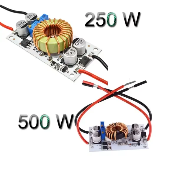 250W/500W 10A Step Up Power Supply DC 8.5V-48V to 10-50V Boost Converter Constant Voltage Current Drive Module Adjustable CC CV
$3.30 – $3.60Price range: $3.30 through $3.60
250W/500W 10A Step Up Power Supply DC 8.5V-48V to 10-50V Boost Converter Constant Voltage Current Drive Module Adjustable CC CV
$3.30 – $3.60Price range: $3.30 through $3.60
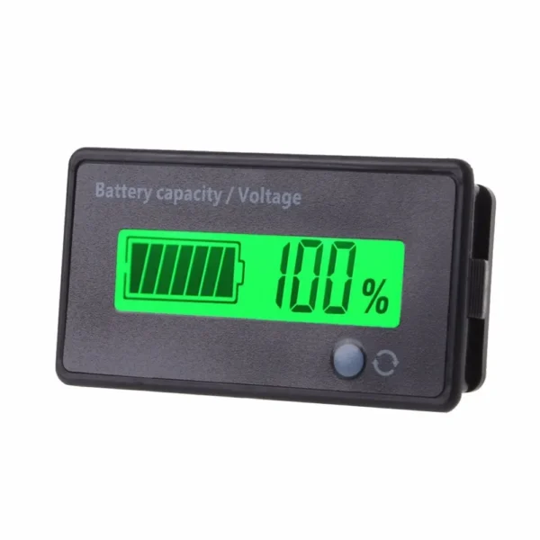 7 to 100V Lead Acid Lithium Battery Capacity Indicator Car Motorcycle Digital Voltmeter Voltage Tester Meter Tool
$4.50
7 to 100V Lead Acid Lithium Battery Capacity Indicator Car Motorcycle Digital Voltmeter Voltage Tester Meter Tool
$4.50
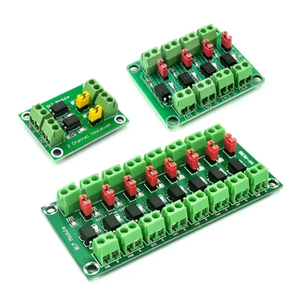 PC817 2/4/8 Channel Optocoupler Isolation Board Voltage Converter Adapter Module 3.6-30V Driver Photoelectric Isolated Module
$2.90 – $4.50Price range: $2.90 through $4.50
PC817 2/4/8 Channel Optocoupler Isolation Board Voltage Converter Adapter Module 3.6-30V Driver Photoelectric Isolated Module
$2.90 – $4.50Price range: $2.90 through $4.50
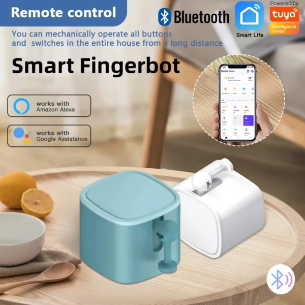 Automate Any Button: Smart Bluetooth Switch for App, Alexa, and Google Home Voice Control
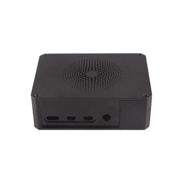 Radxa Metal Case for ROCK 5A, Full Metal Enclosure
$20.90
Radxa Metal Case for ROCK 5A, Full Metal Enclosure
$20.90
EMC testing is expensive, and failing it is worse than the test fee — it costs you a respin, a
We review a lot of boards — some designed in-house, some by other contractors, some by founders doing their own
A wearable PCB is not just a small PCB. It is a board where every constraint that normally has some
The STM32 family is the workhorse of embedded hardware, and almost every project that uses one starts the same way:
The nRF52840 is one of the most popular BLE and multiprotocol chips in the world, and for good reason: it
The ESP32-C6 looks, at first glance, like a small update to the ESP32 family. It has more radios, a newer
No account yet?
Create an Account