What is Loss Tangent and Why Does It Dictate PCB Performance?
In the realm of high-speed and high-frequency electronics, the PCB substrate is not just a mechanical holder for components; it is an active part of the transmission line. Loss Tangent (Df), or Dissipation Factor, quantifies the inefficiency of the dielectric material.
When an alternating current (AC) or high-frequency signal travels through a copper trace, the electromagnetic field extends into the surrounding dielectric material. No dielectric is perfect. The polar molecules within the resin attempt to align with the rapidly changing electric field, creating molecular friction. This friction converts a portion of the electrical signal’s energy into heat.
Loss Tangent is the ratio of this lost energy to the stored energy.
- A lower Df value (e.g., 0.002) means minimal signal loss and high efficiency.
- A higher Df value (e.g., 0.020) means significant signal attenuation and heat generation.
For a hardware engineer, ignoring loss tangent is a direct path to product failure. In a 10 Gbps+ digital link or a 24 GHz radar system, even a few inches of high-Df material can completely close the "eye diagram," rendering the data unreadable or the signal too weak to detect.
The Hidden Costs of Ignoring Loss Tangent in High-Speed Design
Selecting a substrate based solely on cost, without evaluating its Df at your target frequency, introduces severe risks:
- Signal Attenuation and Reach Limitations: The signal degrades over distance. A trace that works perfectly at 1 inch may fail completely at 6 inches, forcing costly board respins or the addition of expensive signal repeaters.
- Impedance Mismatch: Loss tangent is intrinsically linked to the Dielectric Constant (Dk). Materials with high or unstable Df often exhibit Dk variations across the panel and with frequency, making precise impedance control (e.g., 50Ω or 100Ω differential) nearly impossible.
- Thermal Hotspots: The energy lost to the dielectric doesn’t disappear; it becomes heat. In high-power RF applications (like base station amplifiers), this localized heating can accelerate material degradation and reduce the lifespan of the PCB.
Loss Tangent (Df) vs. Dielectric Constant (Dk): Understanding the Duo
While this guide focuses on Loss Tangent, it cannot be discussed without its counterpart, the Dielectric Constant (Dk).
- Dk (Dielectric Constant): Determines the speed of the signal and is the primary variable used to calculate trace width for impedance control.
- Df (Loss Tangent): Determines the strength (amplitude) of the signal over distance.
The Engineering Reality: You need both to be stable. A material might have a great Df, but if its Dk fluctuates wildly with temperature or frequency (as some cheap PTFE blends do), your impedance will drift, causing signal reflections. The ideal high-frequency substrate offers both a low, stable Dk and an ultra-low Df.
Material Comparison: Standard FR-4 vs. Low-Loss Alternatives
Choosing the right material is a balance of performance, manufacturability, and budget. Below is a practical comparison of common PCB substrate categories based on their Loss Tangent (Df) at 10 GHz.
Expert Insight: You do not always need to build an entire board out of expensive ultra-low-loss material. We frequently design and manufacture hybrid stack-ups. For example, we can bond a thin layer of Rogers material (for the critical RF traces) to a thicker, cost-effective FR-4 core (for power and low-speed routing). This optimizes both signal integrity and BOM cost.
Top 3 Manufacturing Pain Points with Low-Loss Materials (And How We Solve Them)
As a hardware developer or supply chain manager, your goal is a high first-pass yield. Low-loss materials are notoriously more difficult to manufacture than standard FR-4. Here is how a professional manufacturing partner mitigates these risks:
1. Drilling Difficulties and Resin Smear
The Pain Point: Advanced low-loss materials (especially PTFE-based ones like Rogers) are either highly abrasive (ceramic-filled) or highly gummy (pure PTFE). Standard FR-4 drilling parameters will cause severe "resin smear," covering the inner-layer copper pads and preventing reliable via plating.
Our Solution: We utilize specialized carbide or diamond-coated drill bits, optimized spindle speeds, and feed rates calibrated specifically for the material datasheet. Furthermore, we employ an aggressive, multi-stage plasma desmear process to ensure 100% removal of resin smear and optimal micro-roughness for reliable copper plating adhesion.
2. Lamination and Bonding Challenges
The Pain Point: Low-loss prepregs have different flow and curing characteristics compared to standard FR-4. Incorrect lamination profiles can result in voids, incomplete resin flow, or excessive thinning of the dielectric layer, which ruins impedance control.
Our Solution: Our CAM (Computer-Aided Manufacturing) engineers use proprietary lamination profiles tailored to the specific material grade. We carefully control the heating rate, pressure application, and cooling cycles to ensure a void-free, dimensionally stable multilayer stack-up with tight Dk/Df tolerances.
3. Surface Roughness and the "Skin Effect"
The Pain Point: At high frequencies, the "skin effect" forces electrical current to travel only on the outer surface of the copper trace. If the copper foil is too rough (like standard electrodeposited copper), the effective path length increases, drastically increasing conductor loss, which compounds the dielectric loss (Df).
Our Solution: For high-frequency builds, we specify Very Low Profile (VLP) or Reverse Treat (RTF) copper foils. These foils have a much smoother surface, minimizing conductor loss and ensuring that the low Df of the substrate is not negated by poor copper selection.
Why Partner with a Professional High-Speed PCB Manufacturer?
Sourcing a low-loss PCB is not a commodity purchase; it is a strategic supply chain decision. The manufacturer you choose must possess the specific technical expertise to handle these demanding materials without compromising yield, schedule, or electrical performance.
We bridge the gap between advanced material science and scalable manufacturing reality. Our end-to-end capabilities ensure your high-reliability project succeeds at every stage:
- Expert Material Consultation & DFM: Before production begins, our engineering team reviews your stack-up and design files. We verify trace/space tolerances, via-in-pad requirements, and thermal relief designs, ensuring your chosen low-loss material is processed correctly to maintain its specified Df and Dk values.
- Seamless Prototyping to Turnkey Assembly: We don’t just fabricate the bare board. We offer complete turnkey PCB assembly manufacturing, managing your entire Bill of Materials (BOM), sourcing authentic high-frequency components, and performing precision SMT assembly. We understand that assembling a Rogers board requires specific thermal profiling to avoid delamination. Explore our integrated workflow: PCB Prototype & Turnkey PCB Assembly Manufacturing.
- Scalable OEM/ODM Bulk Production: When your design is validated, scaling up requires industrial-grade quality control. We adhere to strict IPC-6012 Class 2/3 standards, utilizing Automated Optical Inspection (AOI), controlled impedance testing (with TDR reports), and comprehensive electrical testing. We guarantee consistent quality and competitive pricing for high-volume runs. Request a detailed quote for your next large-scale project: OEM/ODM Bulk Inquiry.
Frequently Asked Questions (FAQ)
Q1: At what frequency do I need to start worrying about Loss Tangent (Df)?
A: As a general rule, if your digital signal edge rate is faster than 1 nanosecond (roughly > 1 Gbps), or your analog/RF frequency exceeds 2-3 GHz, the loss tangent of standard FR-4 will begin to significantly degrade signal integrity. For 5G, PCIe Gen 4/5, or automotive radar, low-loss materials are mandatory.
Q2: Can I mix low-loss materials and standard FR-4 in the same PCB?
A: Yes. This is known as a "hybrid" or "mixed-material" stack-up. It is a highly effective cost-saving strategy. We can laminate a thin layer of low-loss material (like Rogers) only on the layers carrying critical high-speed signals, while using cost-effective FR-4 for the core and power planes.
Q3: How do you verify that the manufactured PCB meets the required impedance and loss specifications?
A: We design dedicated test coupons on the production panel. After fabrication, we use a Vector Network Analyzer (VNA) or Time Domain Reflectometry (TDR) equipment to measure the actual impedance and insertion loss, providing you with a detailed test report alongside your shipment.
Q4: Does a lower Loss Tangent material cost significantly more?
A: Yes, raw material costs for low-loss laminates can be 2x to 5x higher than standard FR-4. Additionally, they require more expensive manufacturing processes (e.g., specialized drilling, plasma desmear). However, this cost is easily justified by the elimination of field failures, reduced need for signal repeaters, and guaranteed product performance.
Don’t Let Substrate Loss Compromise Your Signal
In high-speed and high-frequency electronics, the PCB substrate is the foundation of signal integrity. A poor understanding of Loss Tangent (Df) and its manufacturing implications is a leading cause of costly board respins, delayed time-to-market, and degraded product performance.
By selecting the appropriate low-loss material, adhering to strict DFM guidelines, and partnering with a manufacturer that possesses the specialized equipment and expertise to process these advanced substrates, you transform a potential engineering bottleneck into a competitive advantage.

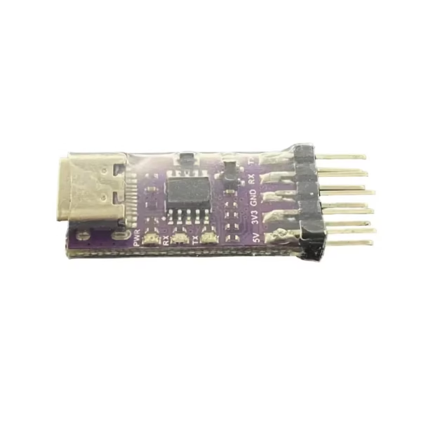 High-Speed USB to TTL UART Adapter CH343P/CH340K Serial Converter for MCU Programming
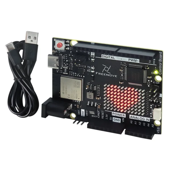 Control Board V5 for Arduino UNO R4 WiFi Mini, Arm Cortex-M4, Onboard ESP32-S3, LED matrix, USB-C, Tutorial Code
$18.90 – $23.90Price range: $18.90 through $23.90
Control Board V5 for Arduino UNO R4 WiFi Mini, Arm Cortex-M4, Onboard ESP32-S3, LED matrix, USB-C, Tutorial Code
$18.90 – $23.90Price range: $18.90 through $23.90
 ESP32-S3 High-Performance Development Board With 3.49inch IPS Capacitive Touch Display, 172 × 640 Resolution
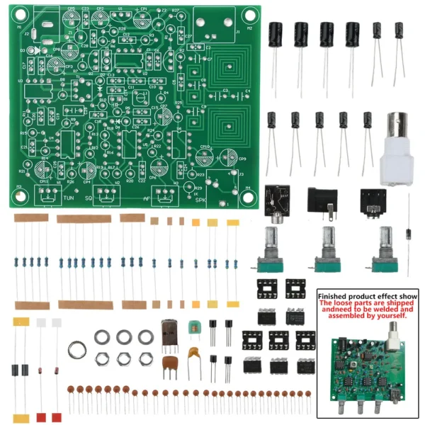 AM Signal Radio Aviation Band Receiver Diy Kits High Sensitivity Air Band Aircraft Tower Calls VHF Antenna Electronic KIT
$15.90
AM Signal Radio Aviation Band Receiver Diy Kits High Sensitivity Air Band Aircraft Tower Calls VHF Antenna Electronic KIT
$15.90
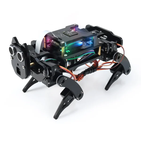 Robot Dog Kit for ESP32-WROVER CAM, Dual-core 32-bit 240MHz, Touch Sensor, Ultrasonic Ranging, Buzzer RGB LED Servo App
$148.90
Robot Dog Kit for ESP32-WROVER CAM, Dual-core 32-bit 240MHz, Touch Sensor, Ultrasonic Ranging, Buzzer RGB LED Servo App
$148.90