
ESP32S Presence Radar
A compact open-hardware development kit for radar-based presence sensing. The ESP32-S3 mainboard connects to the included HLK-LD2410C 24 GHz FMCW radar module through a five-wire cable.
What is included
- 1 × assembled ESP32S Presence Radar R1 mainboard, including ESP32-S3-WROOM-1-N8R8.
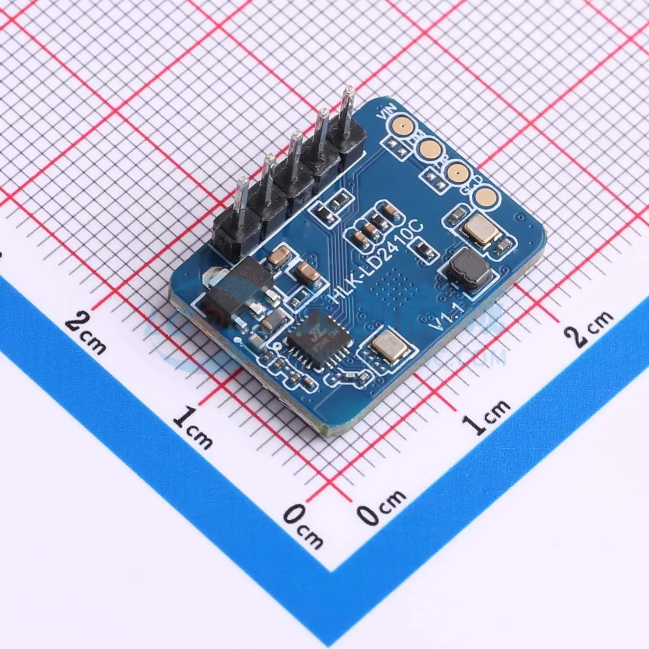
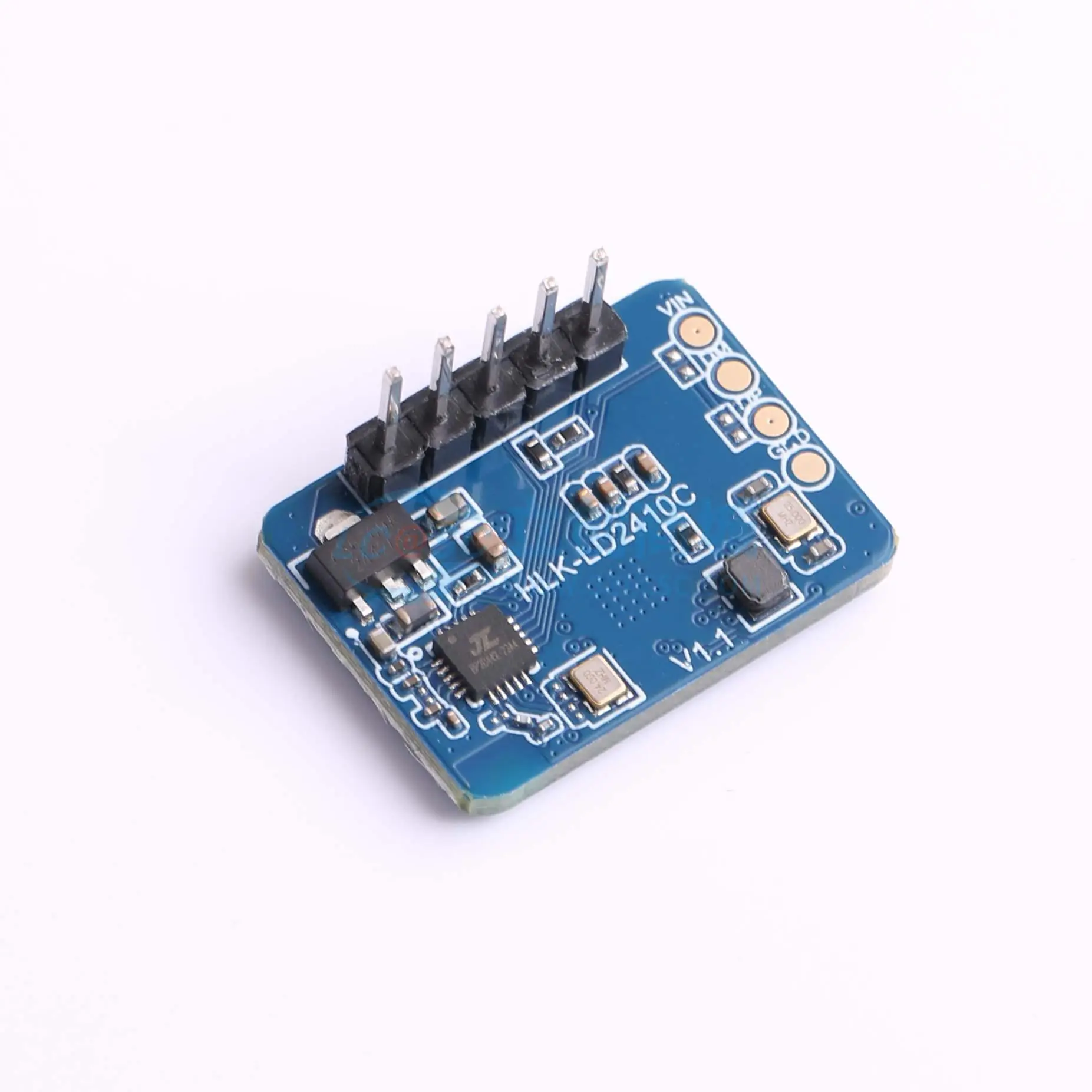
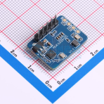
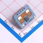
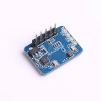
- 1 × HLK-LD2410C radar module.
- 1 × matching five-wire connection cable.
No enclosure, USB cable, power adapter or external Wi-Fi source is included. No battery or charging circuit.
Price and dispatch
USD $29 per kit. Made to order with a 5-day production lead time after order/payment confirmation. Production is arranged for confirmed orders. Dispatch can be arranged immediately after production and checks are complete; shipping transit time is additional.
Mainboard features
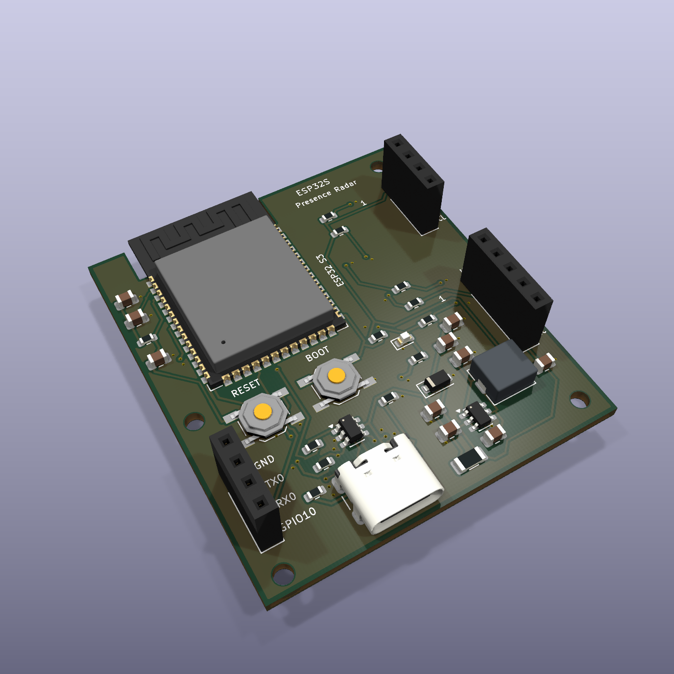
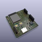
- ESP32-S3-WROOM-1-N8R8 with integrated PCB Wi-Fi antenna.
- 45 × 50 mm, two-layer, 1.6 mm FR-4 mainboard with four M2 mounting holes.
- USB-C 5 V power and native USB data/download.
- 3.3 V buck supply, RESET and BOOT buttons, status LED. Female sockets at J2/J3/J4.
- Radar UART + OUT, I²C expansion and UART0 debug headers, with printed signal legends.
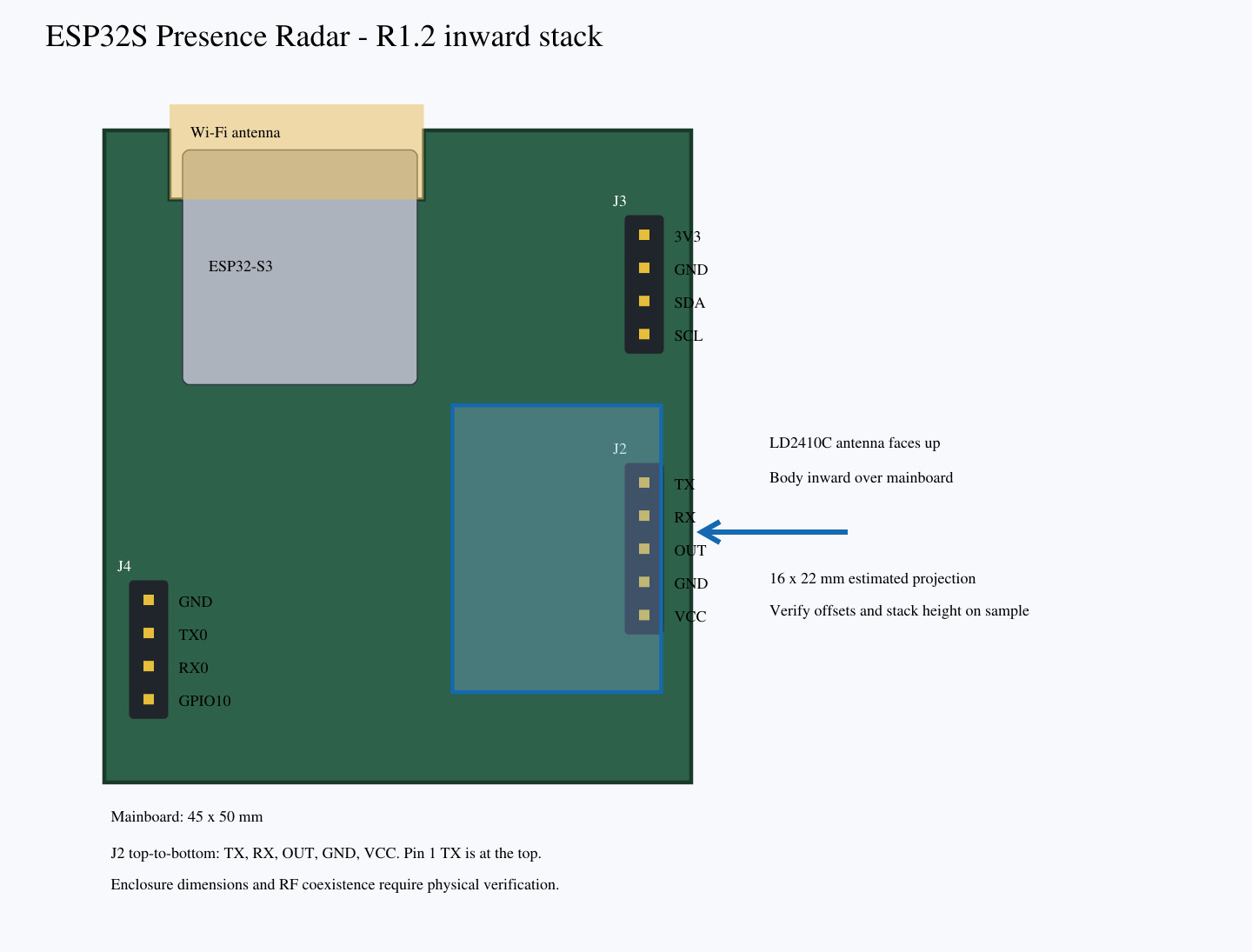
The antenna and USB connector may extend beyond the PCB outline. Mainboard dimensions do not specify the complete kit or enclosure size.
Radar and Wi-Fi CSI
Radar is the primary sensing source. The ESP32-S3 provides a development route for optional Wi-Fi CSI assistance, but complete CSI sensing firmware and calibrated fusion are not supplied. CSI requires appropriate Wi-Fi traffic and environmental calibration. The repository contains an uncompiled radar-only ESPHome example and a Python fusion-rule reference, not ready-to-use combined radar/CSI firmware.
R1.2: female sockets and inward radar stack
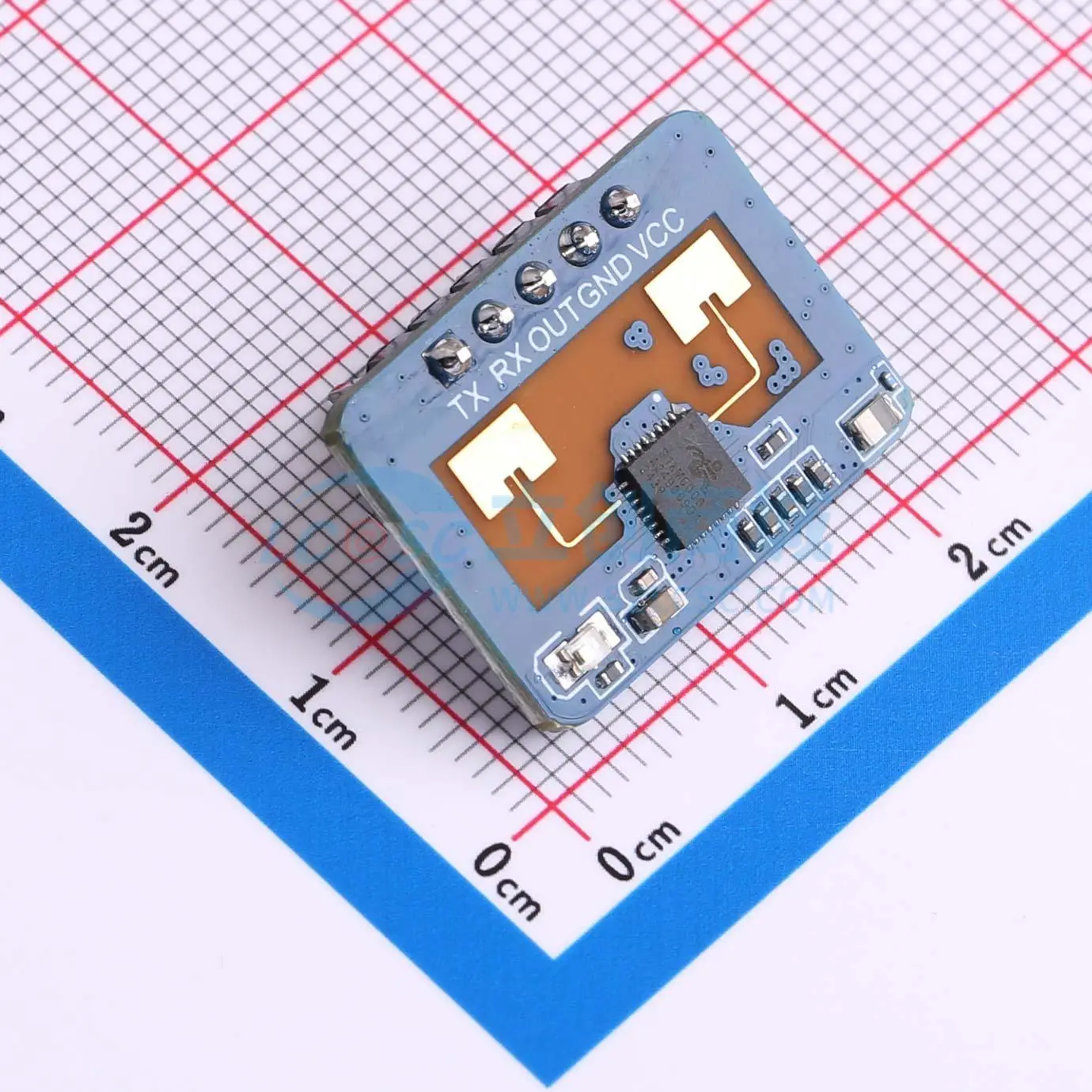
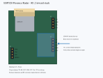
J2, J3 and J4 now use female sockets. J3 is at the upper right; J2 is lower right. Viewed from the component side, J2 runs TX, RX, OUT, GND, VCC from top to bottom. TX is square-pad pin 1 at the top; VCC is pin 5 at the bottom.
The intended direct-plug orientation places the LD2410C antenna face upward and its body inward over the mainboard, helping keep the kit within the mainboard footprint for enclosure planning. The PCB remains 45 × 50 mm. Exact module pin-to-edge offsets, socket and insertion height, underside clearance and final enclosure dimensions must be confirmed on samples. Inward stacking does not prove Wi-Fi/radar coexistence.
The matching cable is included for optional remote mounting. Do not reverse the module: match all five signals before applying power.
Download latest R1.2 KiCad design and manufacturing archive · GitHub project
Development status
R1.2 engineering prototype. Saved KiCad checks report ERC 0, DRC 0, no unconnected items and schematic/PCB parity 0. The six Python fusion-rule tests pass. These are design checks: the hardware has not yet been powered on or qualified for USB, EMC/ESD, temperature, antenna performance or sensing accuracy.
Gallery notes
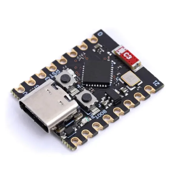
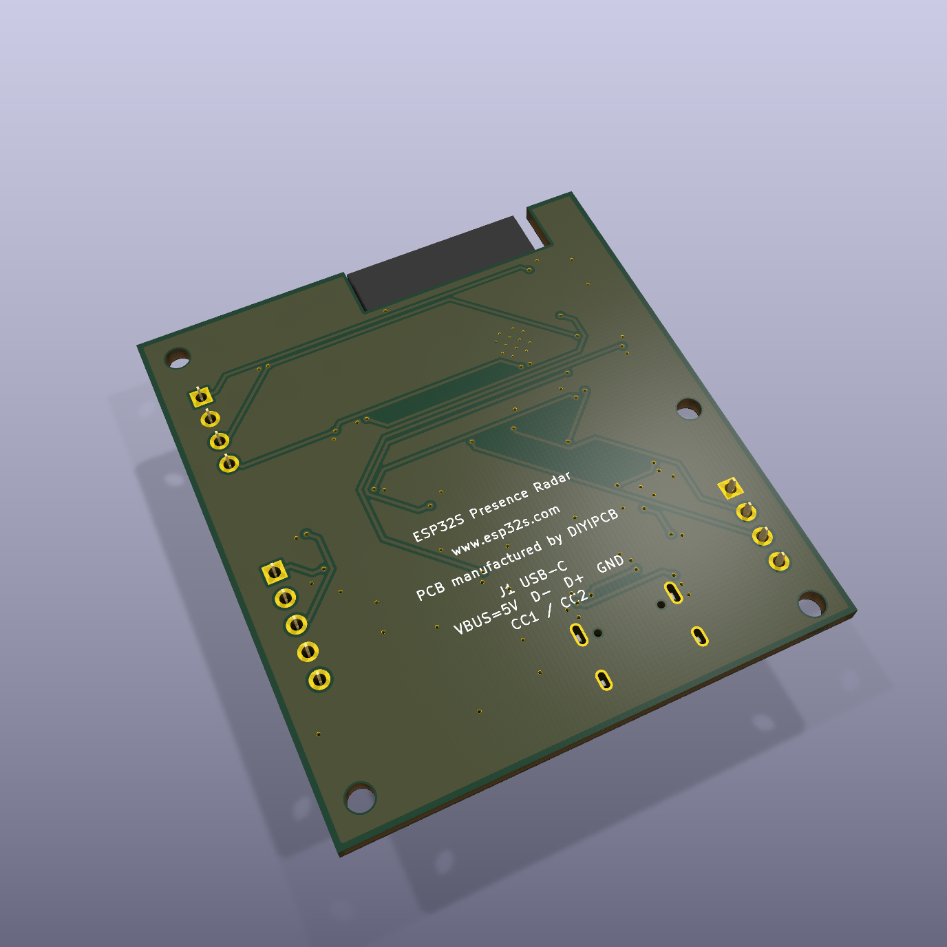
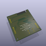
Mainboard pictures are KiCad 3D renders. Radar pictures are reference photos of the included module, not photographs of a complete assembled kit. The mainboard 3D model does not include the external radar or cable.
Documentation and open design
Original hardware uses CERN-OHL-P-2.0; original software examples and documentation use MIT. Redistributed KiCad libraries retain their upstream licences.