
EMC/EMI Checklist Before Your Board Goes to Certification
EMC testing is expensive, and failing it is worse than the test fee — it costs you a respin, a
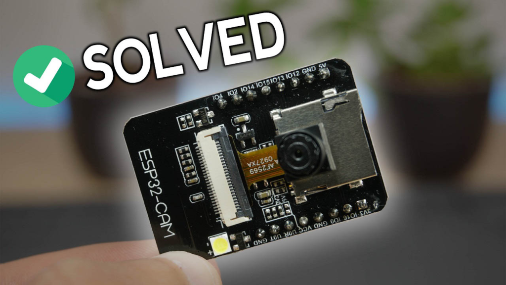
The ESP32-CAM is a remarkably powerful and affordable module for adding video streaming, photo capture, and computer vision to your projects. However, its all-in-one design and specific power requirements can lead to a frustrating array of errors for beginners and experienced makers alike.
This comprehensive guide synthesizes years of community experience and testing to provide clear, actionable solutions. We’ve organized problems from the most critical (uploading code) to the most specific (video latency), complete with technical explanations to help you understand the why behind each fix.
Many problems stem from incorrect initial setup. Before diving into specific errors, verify these three critical points:
Power is Everything: The ESP32-CAM is power-hungry, especially when the camera and flash are active. Always use a stable 5V power source capable of delivering at least 500mA-1A. The 3.3V output from most FTDI programmers is insufficient. A dedicated 5V USB power supply or a high-quality FTDI programmer set to 5V (with a jumper) is mandatory.
Correct FTDI Connection: The most common mistake is incorrect wiring. Double-check this connection table every time:
| ESP32-CAM Pin | FTDI Programmer |
|---|---|
| 5V | 5V (or VCC) |
| GND | GND |
| U0R (RX) | TX |
| U0T (TX) | RX |
| GPIO 0 | GND (for upload) |
Arduino IDE Configuration: In the Arduino IDE, ensure:
Board: AI-Thinker ESP32-CAM
Partition Scheme: Huge APP (3MB No OTA/1MB SPIFFS) (This is crucial to avoid "sketch too big" errors)
Port: Select the correct COM/USB port.
This is the very first hurdle. The “Timed out waiting for packet header” error means your computer cannot initiate communication with the ESP32’s bootloader.
📈 Solution Flowchart:
"Timed Out" Error → 1. Check GPIO 0 is connected to GND → 2. Press RESET button at right moment → 3. Verify FTDI provides 5V → 4. Try another USB cable/port.
Detailed Steps:
The GPIO 0 GND Trick: The ESP32 enters upload (bootloader) mode only when GPIO 0 is held LOW (connected to GND) at boot. This is a physical requirement. Ensure a solid connection.
The Reset Button Timing: The sequence is vital.
Click Upload in the Arduino IDE.
Watch the compile output in the bottom window. As soon as you see "Connecting........_____...", immediately press and release the small RESET button on the ESP32-CAM board.
The upload should then proceed. Missing this timing window is a top cause of failure.
Power Verification: Use a multimeter to check the voltage between the 5V and GND pins on the ESP32-CAM board. It must read 5.0V, not 3.3V. Many cheap USB-to-TTL modules default to 3.3V.
This error signifies the ESP32 cannot communicate with the OV2640 camera module.
Root Causes & Fixes:
Loose Camera Ribbon Cable: This is the #1 culprit. The connector’s locking flap must be lifted fully, the ribbon cable inserted straight and deep, then the flap pressed down firmly to lock it. A partially connected cable causes this error.
Incorrect Board Definition in Code: Your code must specify the exact camera model. In the CameraWebServer example, find the camera_pins.h file or the selection block in the main tab. Uncomment only the correct model. For the standard AI-Thinker board:
// Select your camera model (ONLY UNCOMMENT ONE!)
//#define CAMERA_MODEL_WROVER_KIT
//#define CAMERA_MODEL_ESP_EYE
#define CAMERA_MODEL_AI_THINKER  // <-- UNCOMMENT THIS LINE
//#define CAMERA_MODEL_M5STACK_PSRAM
Faulty or Incompatible Hardware: Some ultra-cheap clones use different pin mappings. Search for your specific board model (e.g., “ESP32-CAM-MB”) to find the correct pin definitions. In rare cases, the camera module or ribbon cable itself is defective.
The ESP32 has a built-in brownout detector (BOD) that resets the chip if the voltage dips too low. This is a clear sign of insufficient power.
Comprehensive Fix:
Abandon Computer USB Ports: Most PC USB ports cannot sustain the current spikes when the camera activates. Use a standalone 5V wall adapter connected to the FTDI programmer’s 5V input or directly to the ESP32-CAM’s 5V pin.
Use Short, High-Quality USB Cables: Long or cheap cables have high resistance, causing voltage drops.
Add Capacitors: Solder a 100µF – 470µF electrolytic capacitor and a 0.1µF ceramic capacitor between the 5V and GND pins on the ESP32-CAM board. This smooths out sudden power demands and is often the definitive fix for brownout and random reset issues.
Weak Signal or No IP Address:
Antenna Selection: The AI-Thinker board has a tiny 0-ohm resistor (looks like a small black rectangle) near the antenna connector. Its position selects the antenna:
Resistor vertical connecting to the PCB trace: Uses the on-board ceramic antenna (weaker).
Resistor horizontal connecting to the connector: Uses an external antenna (stronger). If you don’t have an external antenna attached while the resistor is set for it, you will have virtually no signal.
Power Again: A weak 5V supply directly causes unstable Wi-Fi. Revisit Chapter 3 solutions.
Web Server Won’t Open (Blank Page):
The basic CameraWebServer sketch only supports one client at a time. Ensure you have only one browser tab accessing the ESP32-CAM’s IP address. Close all other tabs.
High Video Latency or “Failed to get the frame on time”:
Reduce Frame Size: In your code, lower the config.frame_size. FRAMESIZE_VGA (640x480) or FRAMESIZE_SVGA (800x600) are much smoother than FRAMESIZE_UXGA (1600x1200).
PSRAM Awareness: If your board lacks PSRAM (pseudo-static RAM), you cannot use high-resolution modes or advanced features like face recognition. Use the following code template to auto-detect and configure for boards without PSRAM:
if(psramFound()){
  // Higher settings for boards WITH PSRAM
  config.frame_size = FRAMESIZE_UXGA;
  config.fb_count = 2;
} else {
  // Lower settings for boards WITHOUT PSRAM
  config.frame_size = FRAMESIZE_SVGA;
  config.fb_count = 1;
}
“Sketch too big” Error: This is solved by going to Tools > Partition Scheme and selecting Huge APP (3MB No OTA).
COM Port Not Available: Ensure you’ve installed the correct USB drivers (CP210x or CH340) for your FTDI programmer. Check your computer’s Device Manager to see if the COM port appears when the programmer is connected.
Legacy vs. New Arduino ESP32 Core: If you are using a post-2.0.0 version of the Arduino ESP32 core, the board definitions have changed. You may now see ESP32-CAM by Espressif Systems instead of “AI-Thinker ESP32-CAM”. The partition scheme option is also different—look for "No OTA (Large APP)" or similar. The new core is recommended as it receives updates and bug fixes.
Follow this sequence for a successful ESP32-CAM session:
Physically Connect: Wire the FTDI with GPIO 0 to GND.
Configure IDE: Select Board, Partition Scheme, and Port.
Upload: Click Upload, then press RESET when prompted.
Disconnect GPIO 0 from GND after a successful upload.
Power Cycle: Press RESET again (with GPIO 0 floating) to run the normal program.
Open Serial Monitor (at 115200 baud) to view the IP address.
By understanding these principles and systematically applying the fixes, you can transform the ESP32-CAM from a source of frustration into a reliable and powerful tool for your creative IoT projects. Share your successful fixes or unique challenges in the comments below to help the community grow!
======================================

No account yet?
Create an Account