
EMC/EMI Checklist Before Your Board Goes to Certification
EMC testing is expensive, and failing it is worse than the test fee — it costs you a respin, a
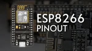
The ESP8266 has revolutionized the world of IoT, offering Wi-Fi capability at an incredibly low cost. However, for beginners and even experienced makers, understanding its pin layout is the first critical step to harnessing its full potential. This guide provides a detailed breakdown of the ESP8266 NodeMCU development board pinout, explaining the function of each pin and crucial practical considerations for your projects.
While the ESP8266 is a chip, it's most commonly used on development boards like the NodeMCU. This board integrates the chip, a USB-to-Serial converter, voltage regulator, and GPIO pins into a developer-friendly package that can be programmed easily via Arduino IDE or other platforms. The pinout we discuss refers to this popular board format.
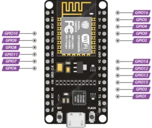
It's vital to remember that the ESP8266 chip has more functions than it has physical pins. Therefore, most pins serve multiple purposes (multiplexing). The numbering on the board (like D0, D1) often differs from the internal GPIO number, which you use in your code.
Digital I/O Pins (GPIOs): Pins like GPIO0, GPIO2, GPIO4, GPIO5, etc., can be configured as standard digital input or output pins using pinMode(), digitalRead(), and digitalWrite() in Arduino code.
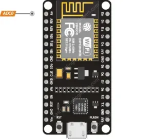
Analog Input (ADC): There is a single Analog-to-Digital Converter pin (A0). It can read voltages from 0V to 3.3V (the operating voltage). Warning: Do not connect more than 3.3V to this pin, or you will damage the board.
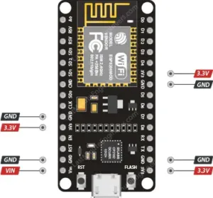
Power Pins:
3.3V: The main operating voltage for the board and connected peripherals.
Vin (VUSB): Can be used to power the board directly with a 5V supply (e.g., from a USB port).
GND: Ground pins.
Special Function Pins:
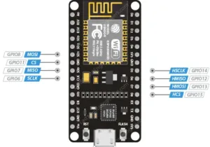
SPI Pins: GPIO12 (MISO), GPIO13 (MOSI), GPIO14 (SCLK), and GPIO15 (CS) provide hardware SPI communication for interfacing with sensors, displays, and SD cards.
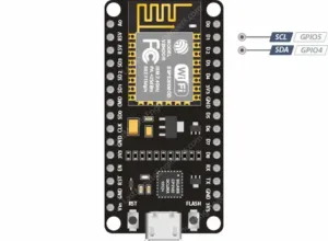
I2C Pins: While not hardware-defined, I2C functionality can be implemented via software on almost any pin. By convention, GPIO4 (SDA) and GPIO5 (SCL) are typically used.
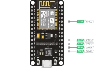
UART Pins: GPIO1 (TX) and GPIO3 (RX) are used for serial communication with a computer or other devices.
Boot Mode Pins (GPIO0 & GPIO2): These pins must be in a specific state (high or low) during boot-up to enter different modes (e.g., Flash Programming Mode vs. Normal Execution Mode). This is why they are often connected to onboard LEDs.
3.3V Logic Level: The ESP8266 is not 5V tolerant. Applying 5V to any GPIO pin will likely destroy the chip. Always use logic level converters when interfacing with 5V devices like most Arduino boards.
Limited Current Sourcing: Each GPIO pin can safely source a maximum of 12mA (with a combined total of ~60mA for all pins). Always use external drivers (like transistors or MOSFETs) for motors or high-power LEDs.
Deep Sleep and Power Saving: To build battery-powered projects, use the deep sleep mode. The RST pin can be connected to GPIO16 (D0) to allow the chip to wake itself up from deep sleep after a predefined period.
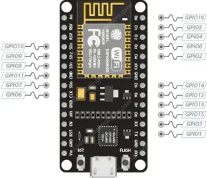
Pins to Avoid: Some pins are used for boot and flash operations. For example, GPIO6 to GPIO11 are internally used for communicating with the flash memory chip and should not be used for other purposes.
The easiest way to program the NodeMCU board is via the Arduino IDE:
Install the ESP8266 board package via the Boards Manager.
Select "NodeMCU 1.0 (ESP-12E Module)" as your board.
Connect the board via USB and select the correct port.
Use the GPIO number (e.g., 16) in your code, not the pin label (e.g., D0).
Wi-Fi Enabled Smart Switch
IoT Temperature and Humidity Sensor
Wireless Plant Watering System
ESP8266 Web Server
By understanding the pin functions and their limitations, you can unlock the powerful capabilities of the ESP8266 and bring your IoT ideas to life reliably.
======================================

No account yet?
Create an Account