
EMC/EMI Checklist Before Your Board Goes to Certification
EMC testing is expensive, and failing it is worse than the test fee — it costs you a respin, a
.BRD File: More Than Just a Layout.brd (board) file is the central repository for a PCB’s physical layout. It contains critical information, including:.brd formats in the industry, and confusing them is a common source of manufacturing delays..brd Files: Historically the most common in the maker, startup, and mid-tier professional markets. Since Autodesk’s acquisition, these are now integrated into Fusion 360, but the legacy .brd extension remains widely used..brd Files: The enterprise standard for complex, high-speed, and high-layer-count designs (e.g., motherboards, aerospace, and advanced telecommunications)..brd file in EAGLE, and vice versa. This proprietary nature is the root cause of many file-handling pain points in PCB fabrication..BRD Files for Manufacturing.brd file for manufacturing introduces three critical risks:.brd file does not always embed the custom component libraries (.lbr in EAGLE) used in the design. If the manufacturer opens the file without your specific library, the software will substitute default footprints. A 0.5mm pitch BGA might be misinterpreted as a standard 1.27mm pitch component, resulting in a completely un-assemblable board..BRD vs. Industry Standard Formats: Why Gerber and ODB++ Rule.brd files, the global PCB manufacturing industry relies on standardized, non-proprietary formats. Understanding this hierarchy is vital for a smooth production run.|
File Format
|
Type
|
Pros for Manufacturing
|
Cons
|
|---|---|---|---|
.brd (EAGLE/Cadence) |
Proprietary Native
|
Contains full design intent, netlist, and 3D data.
|
Version lock-in, missing libraries, requires specific (often expensive) software to view.
|
|
Gerber (RS-274X)
|
Industry Standard
|
Universal, readable by any CAM software, highly reliable for 2D layer visualization.
|
Does not contain netlist data (cannot perform automated netlist comparison), requires multiple files (one per layer).
|
|
ODB++
|
Advanced Standard
|
Single compressed file containing layers, drill data, netlist, and material stack-up. Enables automated CAM processing.
|
Slightly more complex to export correctly from some older EDA tools.
|
|
IPC-2581
|
Next-Gen Standard
|
Rich, intelligent data format endorsed by the IPC. Contains full BOM, stack-up, and manufacturing rules.
|
Adoption is still growing; not all legacy CAM systems support it fully yet.
|
.brd files for a quick, preliminary DFM check, you should always provide Gerber or ODB++ files as the official, legally binding fabrication data..BRD Design for Manufacturing.brd file. Generate a complete Gerber package (including top/bottom copper, solder mask, silkscreen, paste, and outline) and an Excellon drill file..brd file for a DFM review, zip it together with all associated .lbr (library) files and a clear note about the software version used..brd:.brd file functions perfectly in the real world. Learn more about our integrated workflow: PCB Prototype & Turnkey PCB Assembly Manufacturing..brd file directly to a PCB manufacturer?.brd files for a preliminary review, it is highly discouraged as the sole fabrication source. To guarantee accuracy and avoid version/library conflicts, you should always export and submit standard Gerber (RS-274X) or ODB++ files..brd and a Cadence .brd file?.brd file to Gerber?.brd file contain the Bill of Materials (BOM)?.brd file contains physical layout and footprint data, but it does not inherently contain the manufacturer part numbers, quantities, or reference designators needed for assembly. You must export a separate BOM file (usually in CSV or Excel format) for PCB assembly services..brd design?.brd file is a powerful tool for PCB design, but it is not a standalone manufacturing document. Relying on it without proper export procedures or professional oversight is a leading cause of costly PCB respins and project delays.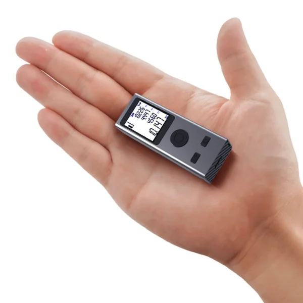 Mini Laser Rangefinder Digital Tape Measure Laser Ruler USB Charge Aluminum Alloy Fuselage Measuring Distance: 30/50/60m
$38.90 – $68.90Price range: $38.90 through $68.90
Mini Laser Rangefinder Digital Tape Measure Laser Ruler USB Charge Aluminum Alloy Fuselage Measuring Distance: 30/50/60m
$38.90 – $68.90Price range: $38.90 through $68.90
 ESP32 Robot Starter Kit for Arduino Solar Charging Best Selling DIY Electronics Artificial Intelligence Robot Complete Kit
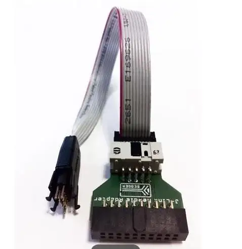 8.06.04 J-Link Needle Adapter 20/10
$180.90
8.06.04 J-Link Needle Adapter 20/10
$180.90
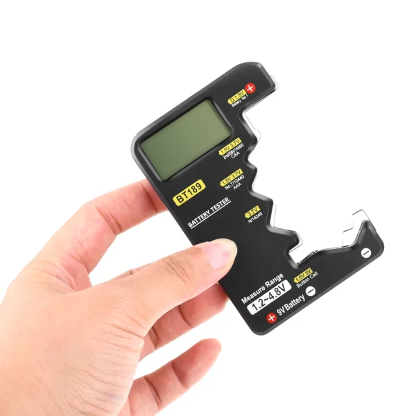 BT189 Ultra-small Battery Tester 9V AAAAA Button Cell Universal Household LCD Digital Display Battery Tester Power Bank Detector
$3.90
BT189 Ultra-small Battery Tester 9V AAAAA Button Cell Universal Household LCD Digital Display Battery Tester Power Bank Detector
$3.90
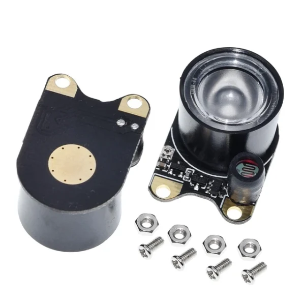 Infrared LED Light 5W 850 Raspberry Pi Camera Board Module Night Vision Infrared IR
$1.80
Infrared LED Light 5W 850 Raspberry Pi Camera Board Module Night Vision Infrared IR
$1.80
EMC testing is expensive, and failing it is worse than the test fee — it costs you a respin, a
We review a lot of boards — some designed in-house, some by other contractors, some by founders doing their own
When a battery-powered product dies too soon, the instinct is to blame the firmware. Surely there is a sleep mode
A wearable PCB is not just a small PCB. It is a board where every constraint that normally has some
The STM32 family is the workhorse of embedded hardware, and almost every project that uses one starts the same way:
The nRF52840 is one of the most popular BLE and multiprotocol chips in the world, and for good reason: it
No account yet?
Create an Account