What is a Rigid PCB? Beyond the Basic Definition
A Rigid Printed Circuit Board (PCB) is the foundational backbone of modern electronics. Unlike flexible PCBs, rigid PCBs are constructed using a solid, non-bendable substrate material that provides exceptional mechanical strength and dimensional stability. Components are securely soldered onto copper traces etched onto the board’s surface, creating reliable electrical connections.
However, from an engineering and procurement perspective, a rigid PCB is more than just a "stiff board." It is a precisely engineered multilayer structure designed to withstand mechanical stress, thermal cycling, and environmental factors while maintaining strict signal integrity. Whether you are developing a consumer IoT device, a medical diagnostic machine, or an aerospace control system, choosing the right rigid PCB specification is the first critical step toward product reliability.
Core Structural Layers of a Rigid PCB (And Why Material Selection Matters)
Understanding the anatomy of a rigid PCB is crucial for making informed design decisions. A standard rigid PCB consists of four primary layers, each serving a distinct functional purpose:
- Substrate Layer (The Foundation): Typically made of woven fiberglass cloth impregnated with an epoxy resin (most commonly FR-4). The quality of the substrate dictates the board’s mechanical strength and thermal performance. For high-reliability applications, selecting a High-Tg (Glass Transition Temperature) material (e.g., Tg170 or higher) is essential to prevent delamination during lead-free soldering or in high-temperature operating environments.
- Copper Layer (The Conductor): Laminated onto the substrate using heat and adhesive. Copper thickness is measured in ounces per square foot (e.g., 1 oz, 2 oz, or heavy copper up to 6 oz). The thickness directly impacts current-carrying capacity and thermal dissipation.
- Solder Mask Layer (The Protector): A polymer layer applied over the copper to insulate the traces, prevent oxidation, and protect against solder bridges during assembly. The choice of solder mask color (green, black, matte) can also affect inspection visibility and thermal absorption.
- Silkscreen Layer (The Identifier): Printed on top of the solder mask, this layer contains component designators, test points, polarity markers, and company logos, which are vital for efficient PCB assembly and troubleshooting.
- Surface Finish (The Interface): Applied to exposed copper pads to ensure solderability and prevent corrosion. Common choices include HASL, ENIG (Electroless Nickel Immersion Gold), and Immersion Silver, each offering different trade-offs between cost, shelf life, and suitability for fine-pitch components.
Rigid vs. Flexible PCBs: Making the Right Choice for Your Project
Choosing between rigid and flexible PCBs often comes down to the mechanical constraints and budget of your application. Below is a detailed comparison to guide your decision-making process:
Expert Insight: If your application does not require dynamic bending or extreme 3D packaging, rigid PCBs are almost always the more cost-effective and reliable choice due to their mature manufacturing ecosystem and lower defect rates.
Advanced Types of Rigid PCBs for Specific Engineering Challenges
Not all rigid PCBs are created equal. Depending on your application’s unique demands, you may need to specify an advanced rigid PCB variant:
- Multilayer Rigid PCBs (4 to 30+ Layers): By stacking alternating layers of copper and prepreg, multilayer boards allow for complex, high-density circuitry in a compact footprint. They are essential for separating power and ground planes, reducing EMI (Electromagnetic Interference), and enabling advanced HDI (High-Density Interconnect) designs.
- Heavy Copper PCBs (≥ 3 oz): Standard 1 oz copper is insufficient for high-power applications. Heavy copper PCBs are designed to handle high currents (e.g., in power supplies, motor controllers, and automotive systems) while significantly improving heat dissipation.
- High-Frequency Rigid PCBs: For RF, microwave, and high-speed digital applications (5G, radar, satellite communication), standard FR-4 causes unacceptable signal loss. Materials like Rogers, Teflon (PTFE), or Arlon are used to maintain strict impedance control and a stable dielectric constant (Dk).
- Metal Core PCBs (MCPCB): Featuring an aluminum or copper base layer, these boards excel in thermal management. They are the industry standard for high-power LED lighting, automotive headlights, and power electronics where heat must be rapidly drawn away from sensitive components.
- High-Tg Rigid PCBs: Designed with a glass transition temperature above 170°C, these boards resist thermal degradation and warping, making them mandatory for automotive under-hood electronics and industrial machinery.
Common Pain Points in Rigid PCB Manufacturing & How to Solve Them
As a hardware developer or procurement manager, you know that transitioning from a CAD design to a physical, reliable product is fraught with challenges. Here are the top pain points we see in rigid PCB manufacturing and how a professional partner mitigates them:
1. Impedance Control Failures
The Pain Point: In high-speed designs, a mismatch in trace impedance (e.g., targeting 50Ω but getting 55Ω) leads to signal reflection, data corruption, and system failure.
Our Solution: A competent manufacturer performs pre-production engineering reviews, adjusting trace width, spacing, and dielectric thickness to guarantee impedance tolerance within ±10%, backed by TDR (Time Domain Reflectometry) testing reports.
2. Thermal Stress and Delamination
The Pain Point: During multiple reflow soldering cycles, low-quality substrates absorb moisture and expand, causing the board to delaminate or vias to crack.
Our Solution: Specifying High-Tg FR-4 or specialized materials, coupled with proper baking procedures before lamination, ensures the PCB withstands thermal shock without compromising structural integrity.
3. DFM (Design for Manufacturability) Blind Spots
The Pain Point: Designers often create boards that are theoretically sound but impossible or highly expensive to manufacture (e.g., annular rings too small, acid traps, or insufficient solder mask slivers).
Our Solution: A value-added manufacturer provides a comprehensive, free DFM check before production begins. This proactive step catches errors early, saving you weeks of respinning and thousands of dollars in wasted prototypes.
Why Partner with a Professional Rigid PCB Manufacturer?
Sourcing a rigid PCB is not just about buying a commodity; it is about securing a reliable supply chain partner who understands your product’s lifecycle from concept to mass production.
At our facility, we bridge the gap between engineering ambition and manufacturing reality. We offer:
- Rapid Prototyping to Turnkey Assembly: Get your designs validated quickly. We provide fast-turn rigid PCB prototypes alongside complete turnkey PCB assembly manufacturing, sourcing components, managing BOMs, and delivering fully tested, box-ready units. Learn more about our seamless prototype-to-production workflow: PCB Prototype & Turnkey PCB Assembly Manufacturing.
- Scalable OEM/ODM Bulk Production: Once your design is validated, scaling up requires rigorous quality control (IPC-A-610 Class 2/3 standards), automated optical inspection (AOI), and flying probe or fixture testing. We support high-volume production with competitive pricing and guaranteed lead times. Request a detailed quote for your next large-scale project here: OEM/ODM Bulk Inquiry.
- End-to-End Traceability: From raw material certification to final shipment, every step of our manufacturing process is documented, ensuring you meet the compliance requirements of medical, automotive, or industrial markets.
Frequently Asked Questions (FAQ)
Q1: What is the standard turnaround time for a rigid PCB prototype?
A: Standard lead times for 2-4 layer rigid PCB prototypes range from 24 hours to 5 days, depending on the complexity, surface finish, and specific testing requirements. Expedited services are available for critical projects.
Q2: Can you manufacture rigid PCBs with controlled impedance?
A: Yes. We routinely manufacture impedance-controlled rigid PCBs. Our engineering team will review your stack-up requirements and adjust the dielectric materials and trace geometries to meet your exact specifications (e.g., single-ended 50Ω or differential 90Ω/100Ω), providing a test coupon report with your shipment.
Q3: What is the minimum trace width and spacing you can achieve on a rigid PCB?
A: For standard FR-4 multilayer boards, we can reliably achieve trace width and spacing down to 3/3 mil (0.075mm). For advanced HDI rigid PCBs utilizing laser-drilled microvias, even finer geometries are possible.
Q4: How do I ensure my rigid PCB design is ready for manufacturing?
A: We highly recommend submitting your Gerber files, drill files, and assembly drawings for a free DFM (Design for Manufacturability) review before placing an order. Our engineers will flag any potential issues related to clearances, annular rings, or thermal relief that could impact yield.
Conclusion: Build Your Next Product on a Solid Foundation
The rigid PCB is the unsung hero of your electronic device. Compromising on its quality, material selection, or manufacturing partner can lead to costly field failures, delayed time-to-market, and damaged brand reputation.
Don’t leave your product’s reliability to chance. Whether you need a quick-turn prototype to validate your latest IoT concept or a trusted partner for high-volume, high-reliability OEM production, we have the expertise, equipment, and quality systems to deliver.

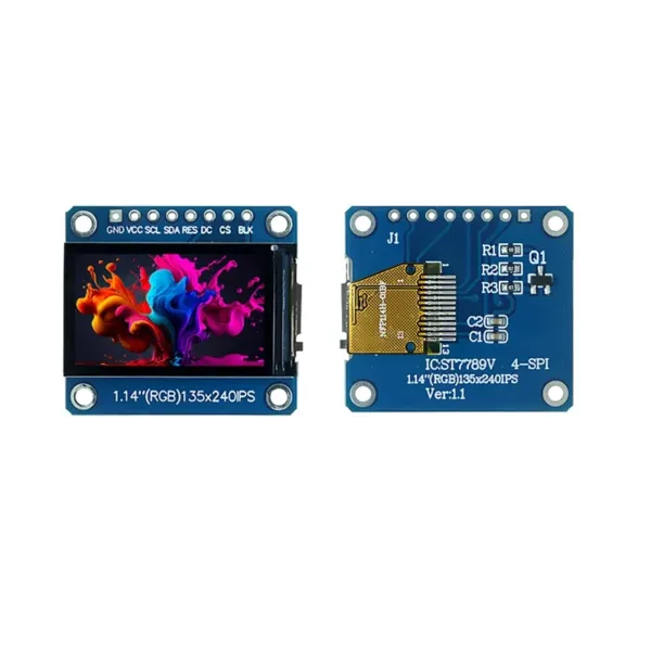 1.14 Inch TFT LCD Display ST7789 SPI Interface 135x240 Resolution Color Screen - Narrow Bar Type Small Screen Module
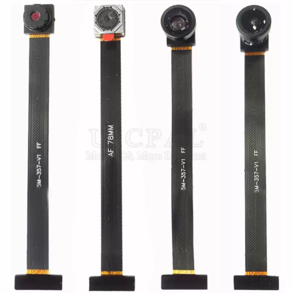 OV5640 Camera Module – 5MP HD, DVP 24-Pin, 78mm, Available in 68°/72°/120°/160° FOV
$6.30 – $8.90Price range: $6.30 through $8.90
OV5640 Camera Module – 5MP HD, DVP 24-Pin, 78mm, Available in 68°/72°/120°/160° FOV
$6.30 – $8.90Price range: $6.30 through $8.90
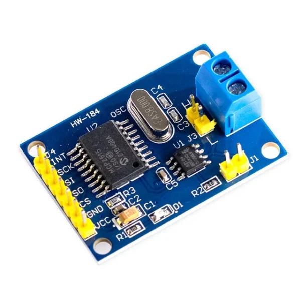 MCP2515 CAN Bus Module Board TJA1050 Receiver SPI For 51 MCU ARM Controller
$3.20
MCP2515 CAN Bus Module Board TJA1050 Receiver SPI For 51 MCU ARM Controller
$3.20
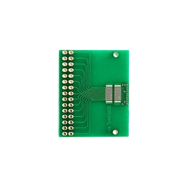 Double row 30pin pitch 0.4mm docking LCM, TFT LCD universal board adapter board test board
$1.00
Double row 30pin pitch 0.4mm docking LCM, TFT LCD universal board adapter board test board
$1.00
 0.91 inch OLED Module OLED 128X32 LCD LED Display Module IIC Communicate For Arduino ROHS Certification-Pin header without soldering