
EMC/EMI Checklist Before Your Board Goes to Certification
EMC testing is expensive, and failing it is worse than the test fee — it costs you a respin, a
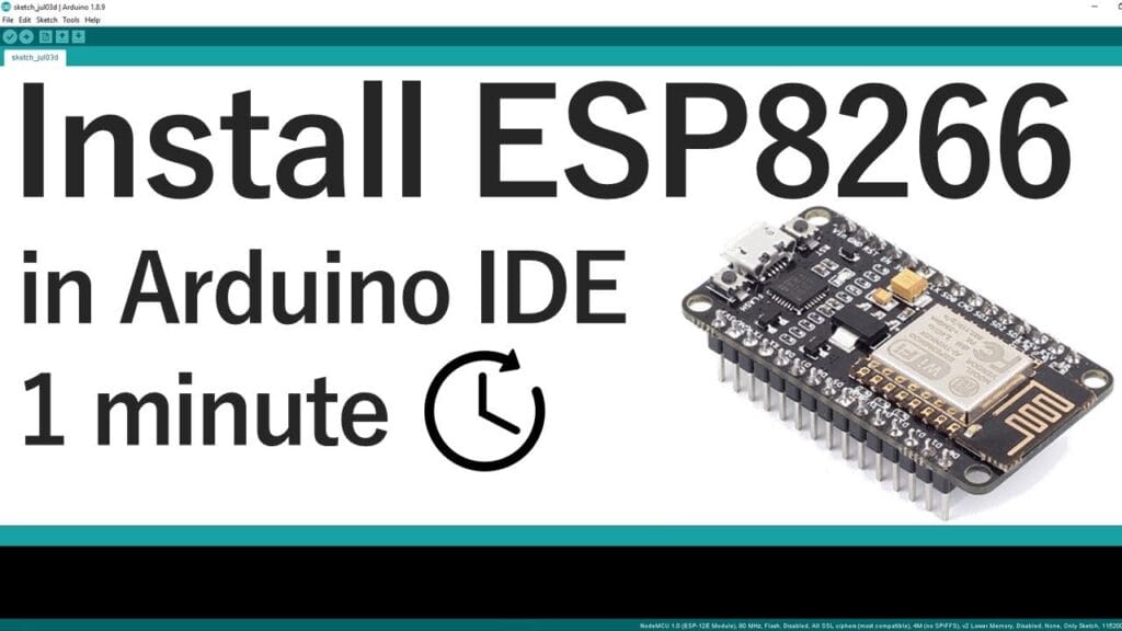
Before proceeding with the ESP8266 board installation, ensure you have these components ready:
Latest Arduino IDE: Download version 2.3.0 or newer from the official Arduino website. Older versions (particularly pre-1.6.4) lack essential framework support for ESP8266.
ESP8266 Development Board: Popular options include NodeMCU (ESP-12E), Wemos D1 Mini, or ESP-01. Each has slightly different programming requirements.
USB Cable: For boards with built-in USB-to-serial converters (like NodeMCU).
FTDI Programmer: Required for boards without USB interfaces (like ESP-01).
Drivers: Depending on your chipset, you may need CP210x or CH340 drivers. We provide updated links in our troubleshooting section.
Critical Note for Linux Users: The Arduino IDE in some Linux repositories (like Ubuntu) may be outdated. Always download directly from Arduino.cc rather than using package managers to avoid version conflicts.
Launch Arduino IDE and navigate to File → Preferences (Windows/Linux) or Arduino IDE → Preferences (macOS).
In the "Additional Boards Manager URLs" field, enter:
http://arduino.esp8266.com/stable/package_esp8266com_index.json
Pro Tip: If you already have ESP32 URLs configured, separate them with commas:
https://dl.espressif.com/dl/package_esp32_index.json, http://arduino.esp8266.com/stable/package_esp8266com_index.json
This single repository contains all necessary tools, board definitions, and libraries for programming ESP8266 devices through Arduino IDE.
Open Tools → Board → Boards Manager...
In the search bar, type "ESP8266"
Locate "ESP8266 by ESP8266 Community" (this is the official package)
Click the "Install" button
The installation typically takes 2-5 minutes depending on your internet connection. You'll see a progress bar indicating the download and installation of:
Xtensa compiler toolchain
ESP8266 board definitions
Core libraries (ESP8266WiFi, ESP8266WebServer, etc.)
Upload tools (esptool, mkSPIFFS)
Version Note: As of January 2026, version 3.1.2 is stable. We recommend against using "latest" (development) versions for beginners due to potential instability.
After installation completes, navigate to Tools → Board → ESP8266 Boards. You'll find approximately 30 different board variants. Selecting the correct one is crucial:
NodeMCU 1.0 (ESP-12E Module): Most common for development boards
Wemos D1 R2 & mini: For Wemos/LOLIN boards
Generic ESP8266 Module: For custom or unidentified boards
ESP-01 Series: For the minimal 8-pin modules
Each selection automatically configures the optimal Flash Size, CPU Frequency, Upload Speed, and other parameters. For generic modules, you may need to adjust these settings manually based on your chip's specifications.
For NodeMCU/ESP-12E boards with built-in LED:
Built-in LED typically connects to GPIO2 (marked as D4 on NodeMCU)
No external components needed
Simply connect via USB cable
For external LED test:
ESP8266 GPIO2 → 220Ω resistor → LED anode (+)
LED cathode (-) → ESP8266 GND
For ESP-01 boards:
Requires FTDI programmer with these connections:
ESP8266 RX → FTDI TX
ESP8266 TX → FTDI RX
ESP8266 CH_PD → 3.3V
ESP8266 GPIO0 → GND (during programming only!)
ESP8266 VCC → 3.3V (NOT 5V!)
ESP8266 GND → FTDI GND
Critical Voltage Warning: ESP8266 is a 3.3V device. Applying 5V will permanently damage the chip. Most FTDI programmers have a 3.3V/5V switch—ensure it's set to 3.3V.
Copy this complete blink sketch:
/*
  ESP8266 Blink Test
  Compatible with all ESP8266 boards
  Turns built-in LED on for 1 second, then off for 1 second
  Complete project details: https://RandomNerdTutorials.com
*/

#define LED_BUILTIN 2  // Most ESP8266 boards use GPIO2 for built-in LED

void setup() {
  pinMode(LED_BUILTIN, OUTPUT);  // Initialize GPIO2 as output
}

void loop() {
  digitalWrite(LED_BUILTIN, LOW);   // Turn LED ON (active LOW on many boards)
  delay(1000);
  digitalWrite(LED_BUILTIN, HIGH);  // Turn LED OFF
  delay(1000);
}
Board-Specific Note: Some boards (like Wemos D1 Mini) have active-high LEDs. If your LED behaves opposite expected, swap HIGH/LOW states in the code.
Select correct COM port (Tools → Port)
Click upload button (right arrow icon)
Observe progress in bottom status bar
Expected success message: "Done uploading"
For ESP-01 and boards without auto-reset: You may need to manually toggle power or press reset after upload.
"Failed to connect to ESP8266: Timed out waiting for packet header"
This indicates incorrect programming mode:
Ensure GPIO0 is grounded during upload
Cycle power to the board
Try different USB cables (some charge-only cables don't transmit data)
Check for loose connections in breadboard setups
"COM Port not found/not available"
Driver issues are the most common cause:
CP210x USB-to-UART Drivers: Download for Windows/Mac/Linux
CH340 Drivers: Download here
FTDI Drivers: Official FTDI VCP drivers
On Windows: Check Device Manager for unrecognized devices (yellow exclamation marks).
"Executable '/bin/xtensa-lx106-elf-g++' not found"
Indicates incomplete toolchain installation:
Close Arduino IDE completely
Delete Arduino15 folder (location varies by OS)
Reinstall ESP8266 board package
Consider using Arduino IDE 2.x instead of 1.x
Board definitions not appearing after installation:
Restart Arduino IDE
Check if multiple Arduino IDE versions conflict
Verify internet connection wasn't interrupted during download
"espcomm_sync failed" / "espcomm_open failed"
Serial communication failure:
Verify correct COM port selection
Close all other serial monitor applications
Disconnect/reconnect USB cable
Try different USB port (avoid hubs if possible)
Incorrect LED behavior:
Verify your board's specific LED pin mapping
Check if LED is active-high or active-low
Test with multimeter to verify GPIO activity
For faster uploads, adjust these settings (Tools menu):
Upload Speed: 921600 baud (if stable), otherwise 115200
Flash Size: Match your chip (usually 4MB)
CPU Frequency: 160MHz for better performance (80MHz for power savings)
Flash Mode: QIO for most boards, DIO for some
ESP8266 has limited flash memory. To conserve space:
Use #include <Arduino.h> instead of #include <ESP8266WiFi.h> when possible
Disable debug output in production code
Use the Tools → ESP8266 Sketch Data Upload for SPIFFS file system
Check for updates quarterly:
Tools → Board → Boards Manager: Update ESP8266 platform
Tools → Manage Libraries: Update critical libraries
Arduino IDE: Check for IDE updates separately
Save these folders regularly:
Arduino15/packages/esp8266 (board definitions)
Arduino/libraries (custom libraries)
Your sketchbook folder
After successful installation, consider these learning paths:
WiFi Connectivity: Learn STA and AP modes with our WiFi tutorials
Web Server: Create control panels accessible from any browser
MQTT Protocol: For IoT home automation systems
Deep Sleep: Battery optimization for wireless sensors
OTA Updates: Wireless programming without USB cables
Q: Can I use both ESP8266 and ESP32 boards simultaneously?
A: Yes, both can coexist in Arduino IDE. Each maintains separate board definitions, libraries, and toolchains. Switch between them via Tools → Board menu.
Q: Why does my ESP-01 require different procedures?
A: ESP-01 lacks USB-to-serial conversion and auto-reset circuitry. It requires manual boot mode control (GPIO0 to GND) and an external programmer.
Q: Is Arduino IDE the best platform for ESP8266?
A: For beginners, yes. For advanced users, PlatformIO (VSCode extension) offers superior dependency management and debugging, but with steeper learning curve.
Q: How do I recover a board that won't program?
A: Use esptool.py directly to erase flash: esptool.py --port COMx erase_flash. Then retry standard programming.
Q: What about Mac Silicon (M1/M2/M3) compatibility?
A: Arduino IDE 2.x runs natively on Apple Silicon. ESP8266 toolchains are fully compatible through Rosetta 2 if needed.
Installing ESP8266 support in Arduino IDE opens doors to affordable, capable IoT development. While the process has matured since 2019, attention to driver installation, board selection, and proper wiring remains crucial. This guide reflects seven years of collective troubleshooting experience—bookmark it for future reference.
No account yet?
Create an Account