Beyond the Basics: What is a Single-Sided PCB and Why Does It Still Matter?
A Single-Sided Printed Circuit Board (PCB) is the foundational architecture of electronics. It consists of a single layer of conductive copper foil laminated onto a non-conductive substrate (such as FR-4, CEM-1, or Aluminum), with electronic components mounted and soldered on that same side.
In an era dominated by 12-layer HDI smartphones and complex multilayer servers, it is tempting to view single-sided PCBs as obsolete. This is a critical misconception. According to industry data, single-sided PCBs still account for a massive portion of global PCB volume. Why? Because for applications that do not require complex signal routing or high-density interconnects, a single-sided design offers unbeatable cost efficiency, simplified supply chains, and superior mechanical reliability (fewer layers mean fewer points of potential delamination).
However, designing a single-sided PCB is not as simple as it looks. The constraint of having only one routing layer introduces unique engineering challenges. Understanding how to navigate these constraints is the key to avoiding costly respins and ensuring your product is truly optimized for mass production.
The Anatomy of a Single-Sided PCB: Material Choices That Impact Cost & Performance
The performance of a single-sided PCB is heavily dictated by its substrate material. Choosing the wrong material to save a few cents can lead to catastrophic field failures.
- FR-4 (Flame Retardant 4): The industry standard woven fiberglass and epoxy resin. While often associated with multilayer boards, thin (0.8mm or 1.0mm) single-sided FR-4 is excellent for applications requiring moderate mechanical strength and standard electrical insulation.
- CEM-1 and CEM-3: Composite epoxy materials. CEM-1 is a paper-based substrate with a single layer of fiberglass cloth on the surface. It is significantly cheaper than FR-4 and is the go-to choice for high-volume, low-cost consumer electronics (e.g., remote controls, basic calculators) where extreme durability is not required.
- Metal Core PCBs (MCPCB / Aluminum Substrate): A specialized form of single-sided PCB where the substrate is aluminum (or occasionally copper). The single copper layer is separated from the metal base by a thermally conductive dielectric layer. This is the absolute standard for high-power LED lighting, automotive headlamps, and power conversion modules, as it pulls heat away from components 10x faster than standard FR-4.
Top 3 Single-Sided PCB Manufacturing Pain Points (And How to Solve Them)
As a hardware developer or supply chain manager, your goal is to maximize yield and minimize unit cost. Here are the most common single-sided PCB failures and how a professional manufacturing partner mitigates them:
1. Routing Congestion and the "Jumper Wire" Trap
The Pain Point: With only one layer for copper traces, avoiding intersecting paths is mathematically challenging. Inexperienced designers often resort to using physical "jumper wires" (zero-ohm resistors or actual wires) to bridge over traces. In high-volume manufacturing, manual jumper insertion is a massive bottleneck, increases labor costs, and introduces a high risk of human error and field failure.
Our Solution: A professional manufacturer provides a complimentary DFM (Design for Manufacturability) review. Our engineers will analyze your layout and suggest component repositioning, trace widening, or the strategic use of 0-ohm resistors placed by SMT machines (not manually) to eliminate hand-soldered jumpers entirely.
2. Thermal Dissipation Bottlenecks
The Pain Point: In a single-sided design, heat generated by power components (like MOSFETs or voltage regulators) has no internal ground plane or thermal vias to dissipate into. The heat is trapped on the surface, leading to premature component degradation or solder joint fatigue.
Our Solution: If your design generates significant heat, we will recommend transitioning to a single-sided Aluminum MCPCB. If FR-4 must be used, our DFM team will optimize your copper pours, ensuring maximum thermal relief and recommending the use of thermally conductive adhesives or heatsinks during the turnkey assembly phase.
3. Wave Soldering Defects (Tombstoning and Bridging)
The Pain Point: Single-sided boards with through-hole components are almost exclusively soldered using wave soldering. If the pad design is asymmetrical or if thermal relief is poorly configured, one side of a component pad heats up faster than the other. This causes surface tension to pull the component upright ("tombstoning") or creates solder bridges between closely spaced pins.
Our Solution: We don't just manufacture the board; we engineer it for assembly. We implement "solder thief" pads at the end of wave soldering trajectories to absorb excess solder, and we balance copper thermal reliefs to ensure uniform heat distribution during the soldering process.
Decision Matrix: When to Choose Single-Sided vs. Double-Sided/Multilayer
Choosing the right PCB architecture is a critical business and engineering decision. Use this guide to validate your design direction:
Expert Insight: If your design can be successfully routed on a single layer without excessive jumper wires, always choose single-sided. The reduction in fabrication cost and assembly complexity will significantly improve your product's profit margin.
Why Partner with a Professional Single-Sided PCB Manufacturer?
Sourcing a single-sided PCB might seem like a commodity purchase, but the difference between an amateur fab shop and a professional partner lies in yield rate, scalability, and assembly integration.
We bridge the gap between cost-effective design and high-reliability manufacturing. Our end-to-end capabilities ensure your project succeeds at every stage:
- From Concept to Validated Prototype: Even simple boards require rigorous validation. We offer rapid-turn single-sided PCB prototyping, coupled with complete turnkey PCB assembly manufacturing. Whether your design requires automated wave soldering for through-hole components or precise top-side SMT placement, we manage the entire BOM, source authentic components, and deliver fully tested units. Explore our seamless workflow: PCB Prototype & Turnkey PCB Assembly Manufacturing.
- Scalable OEM/ODM Bulk Production: When your product hits the market, you need a supplier that can scale from hundreds to hundreds of thousands of units without quality degradation. We utilize automated optical inspection (AOI), strict IPC-A-600 Class 2/3 standards, and optimized panelization to drive down your per-unit cost while guaranteeing consistency. Request a detailed, competitive quote for your next large-scale project: OEM/ODM Bulk Inquiry.
- Material Sourcing Flexibility: Whether you need ultra-low-cost CEM-1 for a disposable consumer product or high-thermal-conductivity Aluminum for an industrial LED array, we have established supply chains to source the exact substrate your application demands at the best market price.
Frequently Asked Questions (FAQ)
Q1: Can I mount SMT (Surface Mount Technology) components on a single-sided PCB?
A: Yes, absolutely. While single-sided PCBs are traditionally associated with through-hole components, top-side SMT assembly is highly common. The SMT components are placed and reflow-soldered on the same side as the copper traces. However, mixing SMT and through-hole on a single-sided board requires careful process planning (usually SMT reflow first, followed by selective wave soldering for through-hole parts), which our assembly team handles seamlessly.
Q2: What is the cheapest PCB material for a single-sided design?
A: For non-demanding, high-volume consumer applications, CEM-1 is typically the most cost-effective single-sided substrate. However, if the board will be subjected to mechanical stress, moisture, or higher operating temperatures, the slight premium for FR-4 is a necessary investment to prevent board cracking or delamination.
Q3: How do you prevent short circuits on a single-sided board with tight trace spacing?
A: We apply a high-quality, liquid photoimageable (LPI) solder mask with strict registration tolerance. Additionally, during our pre-production DFM review, we will flag any trace-to-trace or trace-to-pad spacing that falls below our manufacturing capabilities (typically < 4 mil / 0.1mm) and work with you to adjust the layout before fabrication begins.
Q4: Do you offer panelization services for single-sided PCBs to reduce assembly costs?
A: Yes. For bulk orders, we design custom manufacturing panels (using V-scoring or tab-routing) to maximize the number of boards per panel. This dramatically reduces handling time during both bare-board fabrication and SMT/wave soldering assembly, passing the cost savings directly to you.
Simplicity Requires Expertise
A single-sided PCB may be the simplest form of circuit board, but designing and manufacturing it for high-volume, high-reliability success requires deep expertise. Cutting corners on material selection, DFM review, or assembly process planning will inevitably lead to higher defect rates and hidden costs.
Don’t leave your product’s foundation to chance. Whether you are developing a cost-sensitive consumer gadget or a high-power LED lighting solution, our engineering and manufacturing teams are equipped to optimize your single-sided design for maximum performance and minimum unit cost.

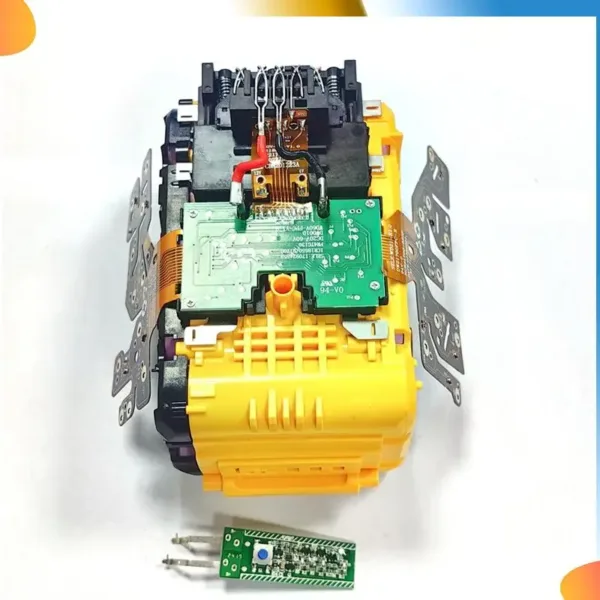 B48A 21700 Lithium Battery Protection Board For Dewalt 20V 60V Battery Lithium Battery Charging Protection Circuit Board
$18.90
B48A 21700 Lithium Battery Protection Board For Dewalt 20V 60V Battery Lithium Battery Charging Protection Circuit Board
$18.90
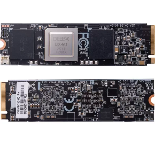 DeepX M1 AI Acceleration Module (M.2 Interface) – Low-Power Computing Expansion Card (25 TOPS) for Rockchip RK3588
$208.60
DeepX M1 AI Acceleration Module (M.2 Interface) – Low-Power Computing Expansion Card (25 TOPS) for Rockchip RK3588
$208.60
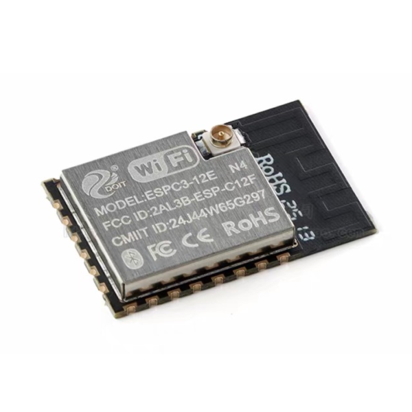 ESPC3-12E WIFI + Bluetooth Dual-Mode Module
$2.80
ESPC3-12E WIFI + Bluetooth Dual-Mode Module
$2.80
 E6 7.3-inch Color E-Paper Frame Solid Wood Design Ultra-Long Standby 800x480 E Ink Photo Frame
$86.70
E6 7.3-inch Color E-Paper Frame Solid Wood Design Ultra-Long Standby 800x480 E Ink Photo Frame
$86.70
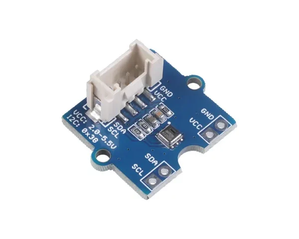 Grove - AHT20 I2C Industrial Grade Temperature and Humidity Sensor
$8.90
Grove - AHT20 I2C Industrial Grade Temperature and Humidity Sensor
$8.90