
EMC/EMI Checklist Before Your Board Goes to Certification
EMC testing is expensive, and failing it is worse than the test fee — it costs you a respin, a
Navigating the GPIO (General Purpose Input/Output) pins of the ESP8266 is a fundamental step for anyone diving into IoT development. This powerful yet affordable microcontroller offers extensive connectivity, but its pin functionality can be confusing. Choosing the wrong pin can lead to projects that fail to boot, behave erratically, or damage components.
This definitive guide provides an authoritative, in-depth reference for the ESP8266 GPIO pins. You'll find clear pinout diagrams for popular development boards, expert recommendations on which pins to use and avoid, and practical insights into their special functions. Our goal is to save you hours of debugging and help you build stable, efficient ESP8266-based devices from the start.
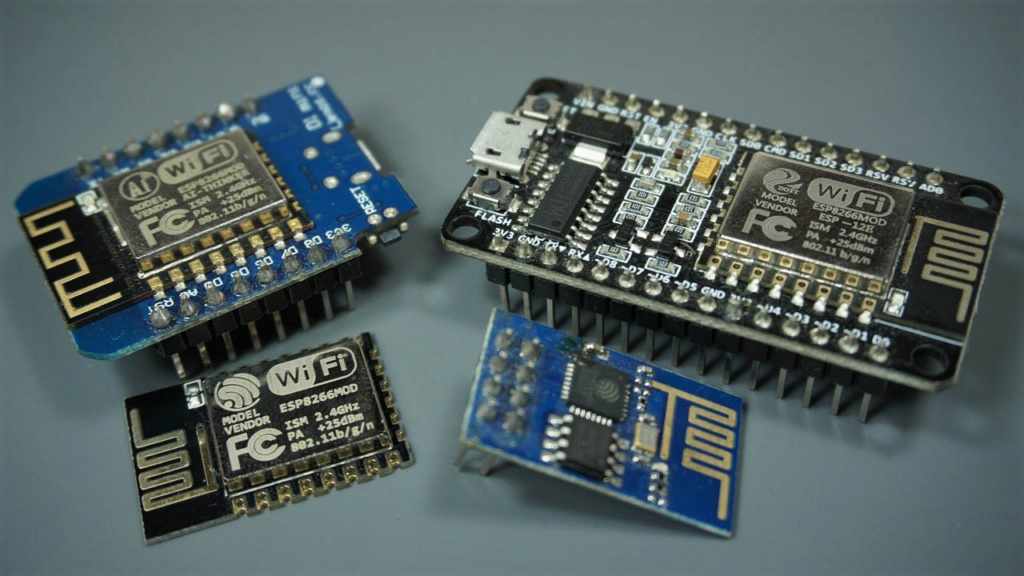
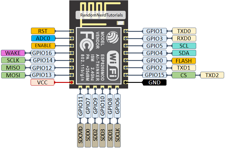
The heart of most modules is the ESP8266 12-E chip, which features 17 GPIO pins. However, not all these pins are accessible on every development board, and some have very specific or restrictive functions. It's crucial to understand that the GPIO number (e.g., GPIO16) often differs from the pin label printed on your board (e.g., D0).
The following illustration shows the pinout of the bare ESP8266 12-E chip, which is essential if you're designing a custom PCB or using the chip directly.
Different boards break out the chip's pins in various configurations. Here are the pinouts for the three most common ESP8266 development platforms.
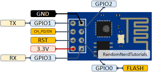
The compact ESP-01 module has limited accessible GPIOs, making pin selection critical.
Key Pins: GPIO0 (Flash), GPIO2 (often onboard LED), TX, RX.
Primary Use: Best for simple, space-constrained applications where only a couple of digital pins are needed.
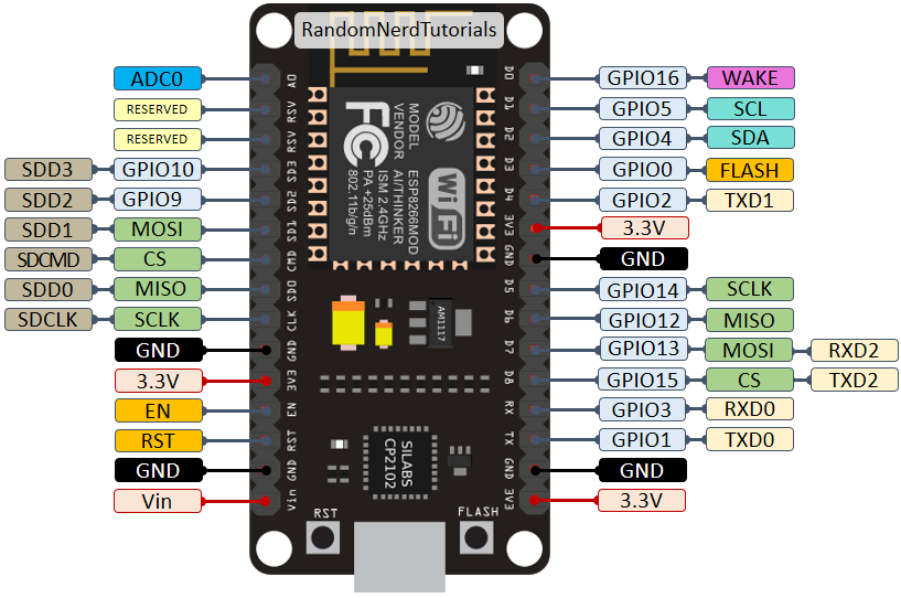
The NodeMCU is a developer favorite, offering many pins broken out to easy-to-use headers.
Key Features: Exposes most usable GPIOs (D0-D8, SD2, SD3), a dedicated ADC pin (A0), and USB-to-serial programming.
Primary Use: Ideal for prototyping and complex projects requiring multiple peripherals (sensors, displays, relays).
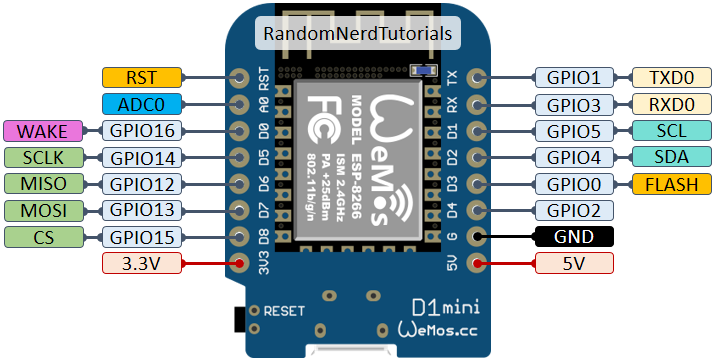
The WeMos D1 Mini strikes a balance between size and capability, resembling an Arduino Nano form factor.
Key Features: Similar pinout to NodeMCU but in a smaller footprint. Often includes a voltage divider on the ADC input.
Primary Use: Perfect for compact, finished projects where a breadboard-friendly size is advantageous.
💡 Pro Tip: We provide a free, downloadable PDF pinout cheat sheet at the end of this article. Print it for quick reference at your workbench.
The ESP8266 is more than just digital pins. Its integrated peripherals include:
17 GPIOs with software-programmable pull-up/pull-down resistors.
SPI (Serial Peripheral Interface) with dedicated pins.
Software I2C (Inter-Integrated Circuit), implementable on almost any pin.
I2S (Inter-IC Sound) for digital audio.
UART (Universal Asynchronous Receiver-Transmitter) for serial communication.
10-bit ADC (Analog-to-Digital Converter) on one pin.
This table is the core of the guide. It cross-references the common board labels (like D1) with the internal GPIO numbers and provides clear, experience-based recommendations.
Legend:
✅ Green (Safe): Generally safe to use for inputs and outputs.
⚠️ Yellow (Use with Caution): Functional but may have boot-time behavior; requires attention.
❌ Red (Not Recommended): Avoid using as general-purpose I/O; reserved for specific functions.
| Board Label | GPIO | Input | Output | Notes & Special Functions |
|---|---|---|---|---|
| D0 | GPIO16 | ⚠️ No interrupt | ⚠️ No PWM/I2C | HIGH at boot. Primarily used to wake up from deep sleep (connect to RST). |
| D1 | GPIO5 | ✅ OK | ✅ OK | Excellent, safe pin. Commonly used as I2C SCL. |
| D2 | GPIO4 | ✅ OK | ✅ OK | Excellent, safe pin. Commonly used as I2C SDA. |
| D3 | GPIO0 | ⚠️ Pulled up | ✅ OK | Connected to FLASH button. Boot fails if pulled LOW. |
| D4 | GPIO2 | ⚠️ Pulled up | ✅ OK | HIGH at boot. Often connected to on-board LED. Boot fails if pulled LOW. |
| D5 | GPIO14 | ✅ OK | ✅ OK | SPI (SCLK). |
| D6 | GPIO12 | ✅ OK | ✅ OK | SPI (MISO). |
| D7 | GPIO13 | ✅ OK | ✅ OK | SPI (MOSI). |
| D8 | GPIO15 | ⚠️ Pulled to GND | ✅ OK | SPI (CS). Boot fails if pulled HIGH. |
| RX | GPIO3 | ✅ OK | ⚠️ TX pin | HIGH at boot. Used for serial programming. |
| TX | GPIO1 | ⚠️ RX pin | ✅ OK | HIGH at boot. Debug output at boot. Boot fails if pulled LOW. |
| A0 | ADC0 | Analog Only | ❌ N/A | Sole analog input. Range is 0-1V (bare chip) or 0-3.3V (most dev boards). |
1. Pins Connected to Internal Flash (GPIO6-GPIO11):
These pins are internally wired to the chip's flash memory. Do not use them for external connections, as it can crash the module.
2. Boot Mode and Pin States:
The ESP8266 reads specific pins during boot. Incorrect voltage levels can prevent it from starting.
Pins That Must Be HIGH (or Floating) at Boot: GPIO0, GPIO2, GPIO15.
Pins That Must Be LOW (or Floating) at Boot: GPIO15.
Pins That Are HIGH at Boot (Can Trigger Relays): GPIO1, GPIO3, GPIO10, GPIO9, GPIO16.
3. Safe Pins for Critical Connections:
GPIO4 (D2) and GPIO5 (D1) are the most stable and problem-free. They have no special boot requirements and don't emit spurious signals during startup, making them the best choice for directly driving relays, MOSFETs, or sensitive sensors.
To enable ultra-low-power deep sleep, connect GPIO16 (D0) to the RST pin. A low pulse on GPIO16 will then trigger a hardware reset, waking the chip.
The ESP8266 has a single 10-bit ADC. On development boards like the NodeMCU, a voltage divider typically scales the input range to 0-3.3V. To measure higher voltages (e.g., a 12V battery), you must add an external voltage divider circuit.
While the ESP8266 lacks hardware I2C, robust software I2C can be implemented. The community standard is:
GPIO5 (D1) as SCL
GPIO4 (D2) as SDA
Using these pins ensures compatibility with most libraries and shields.
Software PWM can be generated on all pins except GPIO16 (D0), with 10-bit resolution. This is perfect for dimming LEDs or controlling servo motors.
The ESP8266 supports hardware interrupts on any GPIO except GPIO16 (D0), allowing you to create responsive code that reacts to button presses or sensor triggers instantly.
Board Won't Boot/Program:
Check GPIO0: It must be pulled HIGH (to 3.3V) for normal boot mode. A common mistake is having a sensor or button pulling it LOW.
Check GPIO15: It must be pulled LOW (to GND) at boot.
Relay Cycles at Power-On: Avoid using pins that are HIGH at boot (GPIO1, GPIO3, GPIO16) for relay control. Use GPIO4 or GPIO5 instead.
Unstable I2C or SPI: Ensure you are using the recommended pins and that your total wire length is not excessive. Use 4.7kΩ pull-up resistors on the I2C lines (SDA/SCL) to 3.3V.
Mastering the ESP8266 pinout is the key to transitioning from frustrating failures to successful, reliable projects. Always start your design by consulting a pinout reference, prioritizing the "safe" GPIOs (D1, D2, D5, D6, D7), and respecting the boot requirements of the cautionary pins.
Ready to build? Explore our hands-on tutorials:
Getting Started with ESP8266: Your first program.
ESP8266 Deep Sleep Guide: Dramatically reduce power consumption.
ESP8266 Web Server: Create a device with a web interface.
📥 Download Our ESP8266 Pinout Reference PDF
[Click here to download] a printable PDF summarizing all pinouts and best practices covered in this guide. Keep it at your desk for quick access!
Was this guide helpful? Do you have a pro tip for managing ESP8266 GPIOs? Share your experience in the comments below to help fellow makers! For more trusted, in-depth tutorials on ESP8266, Arduino, and ESP32, subscribe to our newsletter.
======================================
No account yet?
Create an Account