
EMC/EMI Checklist Before Your Board Goes to Certification
EMC testing is expensive, and failing it is worse than the test fee — it costs you a respin, a
The ESP32 weather station is an exciting and innovative project that brings weather data right to your fingertips. With the integration of the BME280 sensor, you can easily monitor temperature, humidity, and atmospheric pressure. This guide will walk you through the process, highlighting essential details about the ESP32 BME280 I2C installation and the necessary code to make everything function seamlessly.
The ESP32 is a versatile microcontroller with integrated Wi-Fi and Bluetooth capabilities, making it perfect for IoT projects. Its powerful dual-core processor is capable of handling complex tasks, while its array of GPIO pins offers flexibility for various sensors and devices. When combined with a sensor like the BME280, it becomes an excellent platform for creating a DIY weather station that can track climate data in real-time.
The BME280 is a well-regarded sensor used for measuring temperature, humidity, and pressure. It provides accurate readings and is compatible with the I2C communication protocol, which simplifies wiring and makes it easy to connect to microcontrollers like the ESP32. The sensor’s compact size is an added advantage for portable weather stations.
To set up your ESP32 weather station with the BME280 sensor, you will need the following components:
- ESP32 Development Board: This will be the brain of your project.
- BME280 Sensor Module: Ensure it supports I2C communication.
- Connecting Wires: Jumper wires for connections.
- Breadboard (optional): For easy prototyping.
- USB Cable: For powering the ESP32 board and uploading code.
- Arduino IDE: To program the ESP32.
Before diving into the code, let’s handle the wiring. Connect the BME280 module to the ESP32 as follows:
1. BME280 VCC to ESP32 3.3V
2. BME280 GND to ESP32 GND
3. BME280 SDA to ESP32 GPIO 21 (or a different SDA pin if required)
4. BME280 SCL to ESP32 GPIO 22 (or a different SCL pin if required)
This configuration sets up the ESP32 BME280 I2C communication, allowing you to control the sensor directly through the ESP32.
To make things easy, ensure the following libraries are installed in your Arduino IDE:
1. Adafruit BME280 Library
2. Adafruit Sensor Library
3. Wire Library (this is included in the Arduino IDE by default)
You can install these libraries through the Library Manager in your Arduino IDE.
Once the wiring is complete and libraries are installed, it's time for the most exciting part: writing the code. Below is a simple example to get you started with your BME280 ESP32 code:
```cpp
#include
#include
#include
Adafruit_BME280 bme; // I2C
void setup() {
Serial.begin(115200);
// Initialize BME280
if (!bme.begin(0x76)) { // Change to 0x77 if necessary
Serial.println("Could not find a valid BME280 sensor, check wiring!");
while (1);
}
}
void loop() {
// Reading temperature, humidity, and pressure
Serial.print("Temperature = ");
Serial.print(bme.readTemperature());
Serial.println(" *C");
Serial.print("Humidity = ");
Serial.print(bme.readHumidity());
Serial.println(" %");
Serial.print("Pressure = ");
Serial.print(bme.readPressure() / 100.0F);
Serial.println(" hPa");
// Wait for a second before the next reading
delay(1000);
}
```
Connect your ESP32 to the computer via USB and open the Arduino IDE. Select the correct board and port, then upload the code. Open the Serial Monitor once the upload is complete, and you should see real-time weather data being displayed.
Once you've set up your ESP32 weather station, you can explore various enhancements:
- Integrate an LCD display to show the readings without needing a computer.
- Add Wi-Fi functionality to upload the data to a cloud service or display it on a web page.
- Set up alerts for specific weather conditions, such as high humidity or temperature changes.
The ESP32 weather station project with the BME280 sensor is not only a great way to learn about electronics and coding but also offers numerous possibilities for expansion and exploration. With just a few components and some basic coding, you’ll have a fully functional weather monitoring system. By mastering this project, you’ll take your first steps into the exciting realm of IoT and environmental monitoring.
======================================
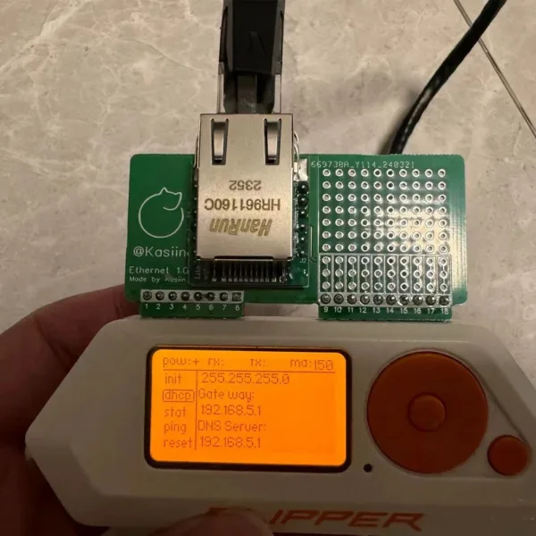 For Flipper Zero Wired Network Test Module Development Board WiFi Devboard for Flipper Zero Attachment Accessory
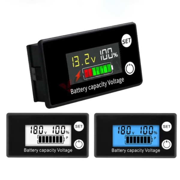 DC 8-100V Battery Capacity Indicator LCD Digital Electricity Meter Lead-acid Lithium LiFe PO4 Voltage Tester for Car Motorcycle
$5.30 – $6.50Price range: $5.30 through $6.50
DC 8-100V Battery Capacity Indicator LCD Digital Electricity Meter Lead-acid Lithium LiFe PO4 Voltage Tester for Car Motorcycle
$5.30 – $6.50Price range: $5.30 through $6.50
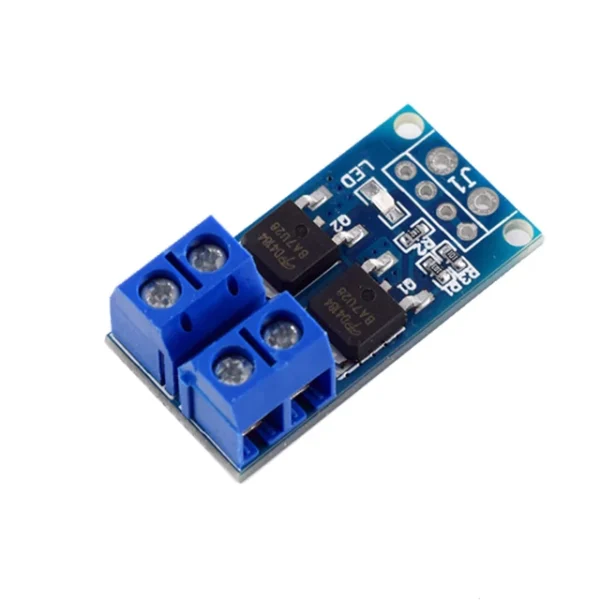 15A 400W High Power MOS Tube Field Effect Switch Trigger Switch Driver Module PWM Adjustable Electronic Switch Control Board
$1.90
15A 400W High Power MOS Tube Field Effect Switch Trigger Switch Driver Module PWM Adjustable Electronic Switch Control Board
$1.90
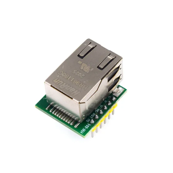 Smart Electronics USR-ES1 W5500 Chip New SPI to LAN/ Ethernet Converter TCP/IP Module
$4.90
Smart Electronics USR-ES1 W5500 Chip New SPI to LAN/ Ethernet Converter TCP/IP Module
$4.90
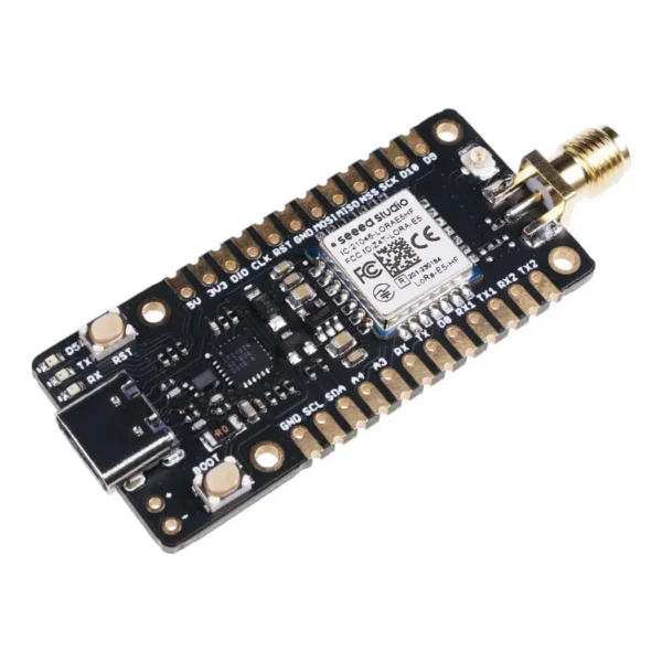 Wio-E5 mini Dev Board - STM32WLE5JC, ARM Cortex-M4 and SX126x embedded, supports LoRaWAN on EU868 & US915
$23.90
Wio-E5 mini Dev Board - STM32WLE5JC, ARM Cortex-M4 and SX126x embedded, supports LoRaWAN on EU868 & US915
$23.90
EMC testing is expensive, and failing it is worse than the test fee — it costs you a respin, a
We review a lot of boards — some designed in-house, some by other contractors, some by founders doing their own
When a battery-powered product dies too soon, the instinct is to blame the firmware. Surely there is a sleep mode
A wearable PCB is not just a small PCB. It is a board where every constraint that normally has some
The STM32 family is the workhorse of embedded hardware, and almost every project that uses one starts the same way:
The nRF52840 is one of the most popular BLE and multiprotocol chips in the world, and for good reason: it
No account yet?
Create an Account