
nRF52840 PCB Layout for BLE Products: Antenna, Matching, and Certification
The nRF52840 is one of the most popular BLE and multiprotocol chips in the world, and for good reason: it
The ESP32-C6 looks, at first glance, like a small update to the ESP32 family. It has more radios, a newer core, and a lower power profile. But if you take a layout you built for the classic ESP32 and drop the C6 into the same footprint and rules, you will find out the hard way that "similar" is doing a lot of work in that sentence.
The C6 is a multi-radio chip. That changes the antenna, the grounding, the power architecture, and even how you think about the board around the module. Here is what actually differs, and where the traps are.
The ESP32-C6 supports Wi-Fi 6 on 2.4 GHz, Bluetooth LE, Thread, and Zigbee — with 802.15.4 available on the variants that include it. For layout purposes, the important consequence is that you are no longer designing a board with a single 2.4 GHz radio path. You are designing a board that has to support multiple protocols sharing the same 2.4 GHz band and the same antenna.
That single fact drives most of the differences below.
The C6 still operates at 2.4 GHz, so the fundamental keep-out rules you know from the classic ESP32 still apply: keep copper out of the antenna region, keep the ground plane continuous under and around the antenna, and give the antenna real physical clearance.
What changes is the bar for performance. Wi-Fi 6 and 802.15.4 are less tolerant of a marginal antenna than plain Wi-Fi 4. A design that "sort of worked" on the classic ESP32 at the edge of range may not hold up when you are relying on the same antenna for Thread mesh links or Zigbee. In practice, this means:
If you use a module with an integrated antenna, the module vendor's keep-out rules are the floor, not the ceiling. If you use a chip-down design with an external antenna, the matching network and layout discipline matter more than they did on the classic part.
The classic ESP32 has one radio path to worry about. The C6 has several, and they share the same ground reference. This makes grounding discipline more important, not less.
The rules are the same ones you already know — a solid, continuous ground plane; short, direct return paths; no plane splits under the radio or its feedline — but the tolerance for sloppiness is lower. A ground plane that is merely "good enough" for one radio can produce degraded performance when several protocols share it.
Practical points:
The C6 is designed for lower-power operation than the classic ESP32, which changes the power design in two directions.
First, the chip can operate at lower supply currents, which means your regulator choice matters differently. A regulator that was fine for a classic ESP32 might be overkill in current but wrong in quiescent current. For battery products especially, you now care about the regulator's own sleep current, not just its peak capability.
Second, because Wi-Fi 6 and 802.15.4 have different transmit duty cycles than classic Wi-Fi, the current profile has different peaks and different averages. Decoupling that was tuned for the old profile may not match the new one. Follow the vendor's reference design for decoupling rather than copying an old ESP32 layout.
The C6 integrates more of the radio, but the crystal and any RF-adjacent passive components still demand care. The classic advice applies with more force:
The reason this matters more on the C6 is that you are relying on the same clocking and matching to serve several protocols. Drift or noise that was a minor annoyance on a single-protocol board becomes a link-quality problem when Thread and Zigbee are in the mix.
The deeper difference between the C6 and older ESP32 parts is on the digital side: the C6 commonly brings out USB Serial/JTAG and a different set of peripheral mappings. If you are moving a design from a classic ESP32 to the C6, do not assume the pinout and interface placement carry over.
For layout, that means:
Because the C6 is a multi-protocol, 2.4 GHz part, certification is more involved than a plain Wi-Fi board. If you use a pre-certified module, much of the radio certification burden is transferred, but only if you follow the module's integration rules exactly — antenna keep-out, no modification to the matching, and so on. If you go chip-down, you own the radio certification work, and the layout is where you either make that easy or expensive.
Design with certification in mind from the start. The cheapest certification is the one your layout does not jeopardize.
If you are porting an existing design, run through this list before you route anything:
We layout ESP32-family boards regularly, including the C6 and its multi-radio siblings. If you are migrating a design or starting from scratch and want the RF and power sections done right, that is our normal work: pcb-layout. If you need the full path from schematic to Gerbers, see pcb-design.
Prototyping and assembly run through PCB PCBA order online.
Send us your C6 design constraints and we will tell you where the risk sits.
The ESP32-C6 is not a drop-in layout for the classic ESP32. Sharing Wi-Fi 6, BLE, Thread, and Zigbee on one 2.4 GHz antenna raises the bar on antenna clearance, feedline impedance, grounding, and enclosure tuning. Power design shifts toward quiescent current, and the digital interfaces — including native USB — need to be re-checked rather than assumed. Certification is more involved, especially chip-down.
Re-derive the layout from the C6 reference design instead of porting an old board, and work through the migration checklist before you route.
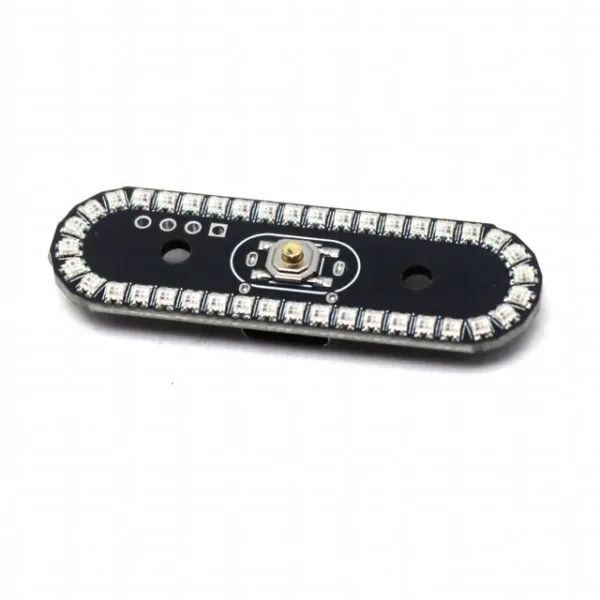 8-Mode Colorful TailLight Model Flow Light Wireless LED Flashing Gradient Breathing Rotating Lamp FOR RC Vehicles Aircraft Drone
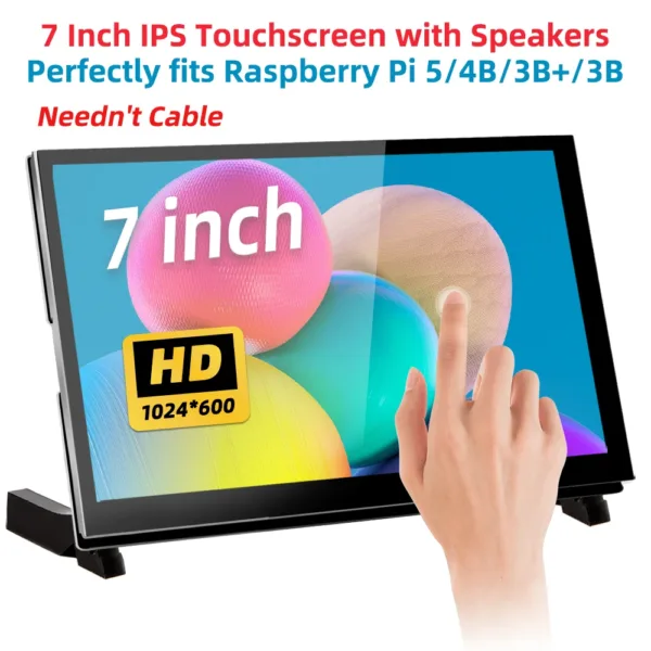 7 inch IPS LCD TFT Display HDMI Touch Screen 1024x600 Resolution Capacitive Touch Screen for Raspberry Pi 5 4 3 3B+ 2
 DC 5V Ultrasonic Atomization Maker Mist Atomizer 500MA DIY Humidifier Type-C Interface Electronic Component Kit
$2.50 – $3.90Price range: $2.50 through $3.90
DC 5V Ultrasonic Atomization Maker Mist Atomizer 500MA DIY Humidifier Type-C Interface Electronic Component Kit
$2.50 – $3.90Price range: $2.50 through $3.90
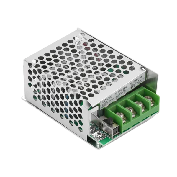 PWM 30A 7-70V DC Motor Speed Controller Module 12V 24V 48V 60V Adjustable Speed Regulator Control Governor Switch
$4.10
PWM 30A 7-70V DC Motor Speed Controller Module 12V 24V 48V 60V Adjustable Speed Regulator Control Governor Switch
$4.10
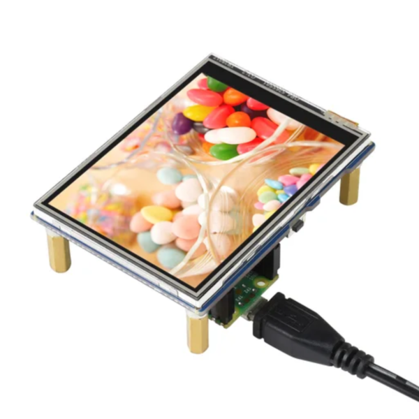 2.8inch Touch Display LCD Module 320×240 Pixels IPS Screen, 262K Colors For Raspberry Pi Pico
$17.90
2.8inch Touch Display LCD Module 320×240 Pixels IPS Screen, 262K Colors For Raspberry Pi Pico
$17.90
The nRF52840 is one of the most popular BLE and multiprotocol chips in the world, and for good reason: it
Most teams frame this as a salary-versus-invoice decision. A layout engineer costs a certain amount per year; a layout shop
Choosing a PCB design service for an IoT product is harder than choosing one for a simple board, because an
If you have ever asked three layout shops for a quote on the same board and gotten three wildly different
Your firmware works. The serial log prints clean, the sensor reads true, and the board boots every time. Then you
Most people who approach a PCB design firm for the first time are not asking for a datasheet. They are
No account yet?
Create an Account