Electronic woven glass fabric is a foundational reinforcement material in Copper Clad Laminates (CCL) and Printed Circuit Boards (PCB). Alongside polymer resin and copper foil, it constitutes the primary triad of rigid PCB materials. The specific properties of the glass fabric directly dictate the mechanical integrity, thermal stability, electrical performance, and processing reliability of the final substrate.
This document provides an engineering-focused analysis of electronic glass fabric, detailing its functional roles, classification standards, and critical selection criteria for high-reliability PCB design.
1. Critical Functions of Glass Fabric in PCB Substrates
Electronic glass fabric is not merely a passive filler; it is an active structural and functional component that addresses several fundamental engineering challenges.
Mechanical Reinforcement and Dimensional Stability
Base resins (e.g., epoxy, phenolic, polyimide, hydrocarbon) inherently lack sufficient rigidity and tensile strength. The glass fabric acts as a structural skeleton, significantly enhancing:
- Tensile and flexural strength.
- Impact resistance.
- Dimensional stability, minimizing thermal expansion and contraction during lamination and machining.
- Warp and twist resistance, which is especially critical for thin-core and large-format panels. Standard E-glass filaments exhibit a tensile strength of approximately 2000–3500 MPa and an elastic modulus of 70–90 GPa, vastly superior to cured resin, thereby elevating the overall mechanical profile of the CCL.
Thermal Management and CTE Control
During soldering, operation, and thermal cycling, the PCB substrate must maintain thermal expansion compatibility with copper foil and mounted components. Standard epoxy resin has a Coefficient of Thermal Expansion (CTE) of roughly 50–70 ppm/°C, while copper is approximately 17 ppm/°C. E-glass fiber has a CTE of only ~5.5 ppm/°C. By compositing glass fabric with resin, the in-plane (X-Y) CTE of the CCL is reduced to 10–18 ppm/°C, closely matching copper. This alignment mitigates thermal stress, preventing plated through-hole (PTH) barrel cracking and interlayer delamination.
Electrical Insulation and Dielectric Performance
While glass fabric is an excellent electrical insulator with high volume and surface resistivity, its dielectric properties differ from the resin matrix.
- Standard E-glass: Dielectric constant (Dk) ~6.6 @ 1 MHz, Dissipation factor (Df) ~0.0012.
- Standard Epoxy Resin: Dk ~3.6–4.0, Df ~0.02. Consequently, a higher glass-to-resin ratio increases the overall Dk of the substrate. While acceptable for standard digital circuits, high-frequency, high-speed applications (e.g., 5G, mmWave radar, high-speed servers) mandate the use of low-dielectric glass fabrics (e.g., NE-glass, D-glass, or quartz) to minimize signal transmission loss and propagation delay.
Processability and Manufacturing Yield
The weave structure of the glass fabric directly impacts downstream PCB fabrication processes, including drilling, routing, desmear, and electroless copper plating:
- High glass hardness accelerates drill bit wear.
- The glass-resin interface creates micro-roughness on the hole wall, which must be optimized to ensure strong plating adhesion.
- Concentrated glass bundles can cause localized resin-glass separation or drill bit deflection.
- Spread or Open Yarn Fabrics: These are mechanically flattened to improve surface flatness and resin impregnation uniformity, which is critical for fine-line imaging and laser microvia drilling.
Long-Term Reliability (CAF Mitigation)
The interface between the glass fiber and the resin matrix is a primary pathway for Conductive Anodic Filament (CAF) failure. Under conditions of high temperature, high humidity, and DC bias, copper ions can migrate along this interface, leading to catastrophic insulation failure. Selecting glass fabrics treated with optimized silane coupling agents, utilizing low-moisture-absorption glass compositions, and employing spread-yarn weaves are proven methods to mitigate CAF risk.
2. Classification and Selection Criteria for Electronic Glass Fabric
Electronic glass fabrics are categorized across multiple dimensions, guiding material selection based on application requirements.
By Glass Composition
- E-Glass: The industry standard for general-purpose FR-4 applications, offering a balanced cost-to-performance ratio.
- Low-Dk/Df Glass (e.g., NE-glass, L-glass): Engineered with specific chemical formulations to reduce dielectric loss. Essential for 5G infrastructure, automotive radar, and high-speed computing.
- Quartz Glass: Offers the ultimate low-loss dielectric performance but at a significantly higher cost, reserved for extreme high-frequency or aerospace applications.
By Thickness and Weight (IPC-4412B Standard)
Electronic fabrics are designated by a four-digit IPC standard code representing thickness and weight. Common designations include:
- 106 / 1080: Ultra-thin fabrics used in High-Density Interconnect (HDI) boards, mobile devices, and IC packaging substrates.
- 2116: A medium-thickness fabric widely used as a bonding sheet (prepreg) in multilayer PCBs.
- 7628: A thicker, heavier fabric used as the core or primary buildup layer in standard multilayer boards.
By Weave Structure and Surface Treatment
- Plain Weave: The most common structure, offering high intersection points, excellent dimensional stability, and balanced mechanical properties in both warp and weft directions.
- Spread/Open Yarn Fabric: Yarns are mechanically expanded and flattened. This reduces surface topography, ensures uniform resin flow, minimizes voids, and significantly lowers CAF risk.
- Surface Treatment: Post-weaving, fabrics undergo high-temperature dewaxing followed by the application of silane coupling agents (amino, epoxy, or vinyl) to optimize the chemical bond between the inorganic glass and the specific organic resin system.
3. Validating Material Compatibility During NPI
Selecting the correct glass fabric is not a theoretical exercise. The interaction between the specific resin system, the glass weave style, and the copper foil dictates the final signal integrity and thermal reliability of the board. For instance, the "fiber weave effect" in high-speed differential pairs can cause severe skew if the glass style is not appropriately chosen or if the traces are not routed at an angle to the weave.
Simulating these material interactions is insufficient. Physical validation of lamination quality, microvia reliability, and high-frequency signal loss is mandatory before committing to mass production. Iterating through multiple material stack-ups can strain R&D budgets.
Hardware and materials engineers can utilize this program to fabricate dedicated test coupons. This allows for empirical verification of resin impregnation quality, laser drilling performance on specific weave styles, and high-speed signal integrity, ensuring the chosen material stack-up meets all design requirements before expensive production tooling is initiated.
4. Scaling Material Validation to Mass Production
Validating a specific glass fabric and resin combination on a small prototype run is fundamentally different from maintaining that consistency across high-volume manufacturing. In mass production, variations in resin flow, lamination pressure, and glass weave tension can lead to defects like resin starvation, weave exposure, or inconsistent impedance.
Transitioning to volume manufacturing requires a partner who enforces strict material and process control. By utilizing our turnkey PCB prototype and assembly manufacturing services, the exact material stack-ups, lamination profiles, and impedance controls validated during your New Product Introduction (NPI) phase are locked directly into the mass-production control plan.
When your design is finalized and you are ready to secure long-term material allocation, initiating an OEM/ODM bulk manufacturing inquiry allows our supply chain and quality engineering teams to integrate your specific substrate requirements into our high-volume Statistical Process Control (SPC) monitoring, ensuring consistent, audit-ready quality across every production batch.
5. Global Industry Landscape
The electronic glass fabric supply chain encompasses electronic glass yarn production and fabric weaving. The market features both vertically integrated giants and specialized high-end manufacturers.
- China Jushi & Taishan Fiberglass: Global leaders in fiberglass production volume, offering comprehensive product lines from standard E-glass to low-dielectric variants, widely supplying the general FR-4 and mid-range thin-core markets.
- Nittobo (Japan): A global technology leader in electronic glass fabrics, particularly renowned for its proprietary NE-glass (low-Dk/Df) and ultra-thin fabrics, which are industry standards for 5G base stations and automotive mmWave radar.
- Honghe Electronics (China): A specialized manufacturer focusing on ultra-thin and extreme-thin electronic glass fabrics (down to 10–20 μm), serving as a critical domestic supplier for HDI and IC packaging substrates.
- Owens Corning / AGY (USA): Providers of high-strength, specialty fiberglass (e.g., S-2 glass, D-glass) catering to extreme aerospace and high-reliability applications.
- Vertically Integrated CCL Manufacturers: Companies like Nan Ya Plastics and Kingboard Laminates maintain internal glass fabric weaving capabilities, ensuring supply chain stability for standard FR-4 materials.
FAQ
Q: Why is spread or open-yarn glass fabric preferred for HDI and high-speed PCBs?
A: Spread yarn fabrics are flattened, creating a smoother surface topography. This ensures more uniform resin impregnation, reduces the risk of voids and Conductive Anodic Filament (CAF) formation, and provides a more consistent dielectric environment for fine-line routing and laser microvia drilling.
Q: How does glass fabric selection impact the Coefficient of Thermal Expansion (CTE) of a PCB?
A: Glass fiber has a much lower CTE (~5.5 ppm/°C) compared to cured epoxy resin (~50-70 ppm/°C). By reinforcing the resin with glass fabric, the in-plane CTE of the composite substrate is reduced to 10-18 ppm/°C, which closely matches the CTE of copper foil, thereby preventing thermal stress failures like PTH barrel cracking.
Q: What is the "fiber weave effect" in high-speed PCB design?
A: Because glass bundles and resin pockets have different dielectric constants (Dk), a high-speed differential pair routed parallel to the glass weave can experience uneven propagation delays, leading to signal skew and eye diagram closure. This is mitigated by using spread-yarn fabrics, zigzag routing, or rotating the PCB panel during fabrication.
Q: Can standard E-glass be used for 5G or high-speed server applications?
A: Generally, no. Standard E-glass has a relatively high Dk and Df, which causes excessive signal attenuation and loss at high frequencies. These applications require specialized low-dielectric glass formulations, such as NE-glass or quartz, to maintain signal integrity.
The selection of electronic woven glass fabric is a critical materials engineering decision that directly impacts the mechanical, thermal, and electrical reliability of a PCB. Moving beyond generic specifications to understand weave structure, dielectric properties, and resin compatibility is essential for designing robust, high-performance electronic systems. If your upcoming projects require rigorous material validation and scalable manufacturing processes, our engineering team is prepared to support your transition from NPI prototyping to high-volume production.

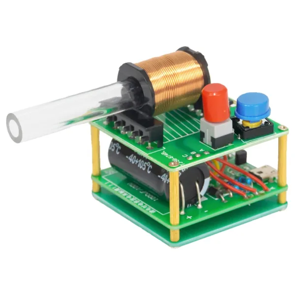 DIY Electronic Kit Mini Electromagnetic Gun 100V High Voltage DIY Soldering Build Kit Micro Interface DC5V Fast Charging
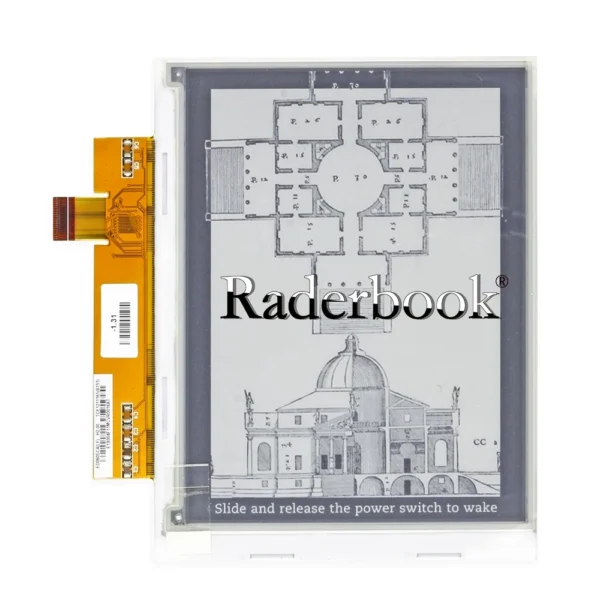 ED060SC4 ED060SC4(LF) 6" e-ink LCD screen for Pocketbook 301/603/611/612/613 PRS-505
$18.90
ED060SC4 ED060SC4(LF) 6" e-ink LCD screen for Pocketbook 301/603/611/612/613 PRS-505
$18.90
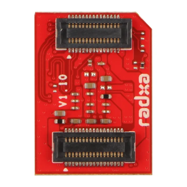 Radxa UFS Storage Module - 128GB
$59.80
Radxa UFS Storage Module - 128GB
$59.80
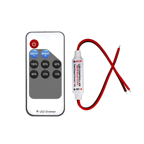 Mini LED Single Color dimmer DC 5V 12V 24V 6A 5050 2835 Strip Lights Constant Voltage PWM Signal Controller with RF 9-Key Remote
$1.90
Mini LED Single Color dimmer DC 5V 12V 24V 6A 5050 2835 Strip Lights Constant Voltage PWM Signal Controller with RF 9-Key Remote
$1.90
 DC-DC USB step-up/step-down power supply voltage regulator module 5V to 3.3V 9V 12V 24V converter output DC 1.2V-24V
$3.90
DC-DC USB step-up/step-down power supply voltage regulator module 5V to 3.3V 9V 12V 24V converter output DC 1.2V-24V
$3.90