
EMC/EMI Checklist Before Your Board Goes to Certification
EMC testing is expensive, and failing it is worse than the test fee — it costs you a respin, a
The ESP32's built-in WiFi makes it an ideal microcontroller for creating standalone web servers to control devices from any browser. This comprehensive guide walks you through building a responsive web server with the Arduino IDE to control outputs like LEDs or relays. The server operates on your local network and can be accessed from smartphones, tablets, or computers. Updated for 2026, this tutorial provides the complete code, step-by-step wiring, and an in-depth explanation of how it all works.
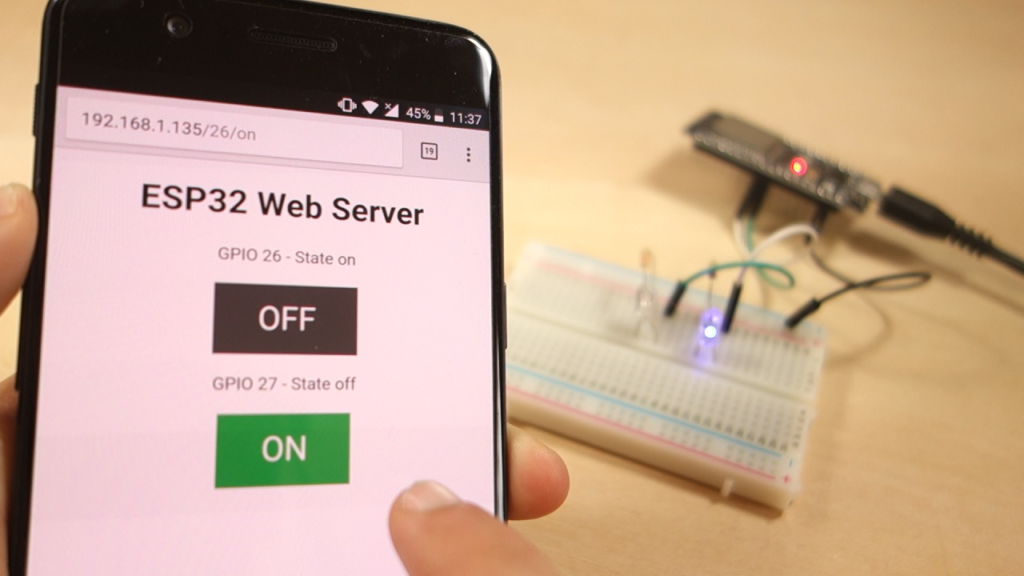
This project transforms your ESP32 into a dedicated web server that provides a simple, mobile-friendly interface. You will build a system where:
Two LEDs (representing any output device) are connected to the ESP32's GPIO pins.
The ESP32 connects to your local WiFi network.
You type the board's IP address into any web browser to access a control page.
Clicking buttons on the webpage instantly turns the connected LEDs ON or OFF.
This foundational project demonstrates the core principles of IoT control, which you can later scale to manage relays for lights, motors, sensors, or other home automation devices.
Arduino IDE (version 2.x or later recommended) installed on your computer.
ESP32 Board Package installed in the Arduino IDE. You can install it via Tools > Board > Boards Manager... and searching for "ESP32 by Espressif Systems".
Basic familiarity with uploading code to the ESP32.
You will need the following components:
| Component | Quantity | Notes |
|---|---|---|
| ESP32 Development Board (e.g., DOIT DEVKIT V1) | 1 | Most 30-pin or 36-pin boards work. |
| 5mm LED | 2 | Any color. |
| Resistor (220Ω to 330Ω) | 2 | For current limiting. |
| Breadboard | 1 | For easy prototyping. |
| Jumper Wires (Male-to-Male) | Several | For making connections. |
| Micro-USB Cable | 1 | For power and programming. |
Connect the components as shown below. Always double-check your connections before powering the circuit.
(Insert clear diagram or schematic here showing:
ESP32 GPIO26 → Resistor → LED Anode (Long leg); LED Cathode → GND.
ESP32 GPIO27 → Resistor → Second LED Anode; LED Cathode → GND.
ESP32 Vin/GND to breadboard power rails if needed.
)
⚠️ Important: The ESP32's GPIO pins are not 5V tolerant. Use the correct 3.3V logic levels. Ensure the longer leg (anode) of the LED connects to the GPIO pin via a resistor, and the shorter leg (cathode) connects to ground.
Copy the complete code below into your Arduino IDE. You must update the ssid and password variables with your own WiFi network credentials before uploading.
/*********
 * ESP32 Standalone Web Server
 * Controls two LEDs connected to GPIO 26 and GPIO 27
 * Complete project details: https://www.randomnerdtutorials.com
 * Based on the Arduino WiFi library examples
 *********/

#include <WiFi.h>
#include <WiFiClient.h>

// ======== CONFIGURE YOUR NETWORK ========
const char* ssid = "YOUR_WIFI_NETWORK_NAME";  // Replace with your SSID
const char* password = "YOUR_WIFI_PASSWORD";   // Replace with your password

// ======== SERVER & PIN CONFIGURATION ========
WiFiServer server(80); // Set web server port to 80 (standard HTTP)

// Define GPIO pins for the outputs
const int ledPin_26 = 26;
const int ledPin_27 = 27;

// Variables to track the current state of each output
String state_26 = "off";
String state_27 = "off";

// Header variable to store HTTP request
String header;

// Timing variables for connection timeout (2000ms = 2s)
unsigned long currentTime = millis();
unsigned long previousTime = 0;
const long timeoutTime = 2000;

// ======== SETUP FUNCTION ========
void setup() {
  Serial.begin(115200); // Start serial communication for debugging

  // Initialize GPIO pins as outputs and set to LOW (OFF)
  pinMode(ledPin_26, OUTPUT);
  pinMode(ledPin_27, OUTPUT);
  digitalWrite(ledPin_26, LOW);
  digitalWrite(ledPin_27, LOW);

  // Connect to WiFi Network
  Serial.print("Connecting to ");
  Serial.println(ssid);
  WiFi.begin(ssid, password);

  while (WiFi.status() != WL_CONNECTED) {
    delay(500);
    Serial.print(".");
  }

  // Print connection details
  Serial.println("\nWiFi connected successfully!");
  Serial.print("Board IP Address: ");
  Serial.println(WiFi.localIP()); // <- CRITICAL: You need this IP to access the server

  server.begin(); // Start the web server
}

// ======== MAIN LOOP ========
void loop() {
  WiFiClient client = server.available(); // Listen for incoming client connections

  if (client) { // A new client has connected
    Serial.println("New Client Connected.");
    String currentLine = ""; // Buffer for incoming data
    currentTime = millis();
    previousTime = currentTime;

    // Stay connected while client is active and within timeout window
    while (client.connected() && (currentTime - previousTime <= timeoutTime)) {
      currentTime = millis();

      if (client.available()) { // Data is available to read from client
        char c = client.read(); // Read one byte
        Serial.write(c);        // Echo to Serial Monitor (optional)
        header += c;            // Append to the header string

        if (c == '\n') { // End of a line in the HTTP request
          // If the line is blank, the HTTP request has ended
          if (currentLine.length() == 0) {
            // Send a standard HTTP response header
            client.println("HTTP/1.1 200 OK");
            client.println("Content-type:text/html");
            client.println("Connection: close");
            client.println(); // Blank line marks end of header

            // ======== CONTROL LOGIC ========
            // Check the request URL and control GPIOs accordingly
            if (header.indexOf("GET /26/on") >= 0) {
              Serial.println("Turning GPIO 26 ON");
              state_26 = "on";
              digitalWrite(ledPin_26, HIGH);
            } else if (header.indexOf("GET /26/off") >= 0) {
              Serial.println("Turning GPIO 26 OFF");
              state_26 = "off";
              digitalWrite(ledPin_26, LOW);
            } else if (header.indexOf("GET /27/on") >= 0) {
              Serial.println("Turning GPIO 27 ON");
              state_27 = "on";
              digitalWrite(ledPin_27, HIGH);
            } else if (header.indexOf("GET /27/off") >= 0) {
              Serial.println("Turning GPIO 27 OFF");
              state_27 = "off";
              digitalWrite(ledPin_27, LOW);
            }

            // ======== GENERATE THE HTML WEB PAGE ========
            client.println("<!DOCTYPE html><html>");
            client.println("<head><meta name=\"viewport\" content=\"width=device-width, initial-scale=1\">");
            client.println("<title>ESP32 Web Server</title>");
            client.println("<style>");
            client.println("html {font-family: Arial, sans-serif; display: inline-block; text-align: center;}");
            client.println(".button {background-color: #4CAF50; border: none; color: white; padding: 15px 32px;");
            client.println("text-decoration: none; display: inline-block; font-size: 18px; margin: 4px 2px; cursor: pointer;}");
            client.println(".button-off {background-color: #555555;}"); // Style for the OFF button
            client.println("</style></head>");
            client.println("<body>");
            client.println("<h1>ESP32 Web Server Control Panel</h1>");

            // Display control for GPIO 26
            client.println("<p>LED on GPIO 26 is: <strong>" + state_26 + "</strong></p>");
            if (state_26 == "off") {
              client.println("<p><a href=\"/26/on\"><button class=\"button\">TURN ON</button></a></p>");
            } else {
              client.println("<p><a href=\"/26/off\"><button class=\"button button-off\">TURN OFF</button></a></p>");
            }

            // Display control for GPIO 27
            client.println("<p>LED on GPIO 27 is: <strong>" + state_27 + "</strong></p>");
            if (state_27 == "off") {
              client.println("<p><a href=\"/27/on\"><button class=\"button\">TURN ON</button></a></p>");
            } else {
              client.println("<p><a href=\"/27/off\"><button class=\"button button-off\">TURN OFF</button></a></p>");
            }

            client.println("</body></html>");
            client.println(); // End of response

            break; // Exit the while loop
          } else { // If we got a newline, clear the current line buffer
            currentLine = "";
          }
        } else if (c != '\r') { // Ignore carriage return characters
          currentLine += c; // Add character to the current line
        }
      }
    }
    // Clear the header variable and close the connection
    header = "";
    client.stop();
    Serial.println("Client disconnected.");
    Serial.println();
  }
}
In the Arduino IDE, select your ESP32 board under Tools > Board.
Select the correct COM port under Tools > Port.
Click the upload button.
Open the Serial Monitor (Tools > Serial Monitor).
Set the baud rate to 115200.
Press the EN/RST button on your ESP32 board.
Watch the output. After "WiFi connected successfully!", you will see a line like:
Board IP Address: 192.168.1.XXX
Copy this IP address.
On any device connected to the same local WiFi network (phone, laptop, tablet), open a web browser (Chrome, Safari, Firefox, etc.).
In the browser's address bar, type the IP address you copied (e.g., http://192.168.1.XXX) and press Enter.
The ESP32 control panel webpage should load, displaying two buttons for controlling the LEDs.
Click the "TURN ON" button for GPIO 26. The corresponding LED should light up, and the webpage will update its state to "on".
Click the "TURN OFF" button to turn it off.
Repeat for GPIO 27. Observe the Serial Monitor to see the real-time HTTP requests (GET /26/on) as you click.
The WiFi.h library provides all necessary functions. The WiFiServer server(80); object listens for incoming connections on port 80, the standard port for HTTP traffic. The connection process in setup() is blocking but includes visual feedback via the Serial Monitor.
The core of the server is in the loop(). The server.available() function checks for a new client. When a browser connects, it sends an HTTP GET request. The code reads this request character by character, storing it in the header string.
The program searches the incoming header for specific URL patterns:
"GET /26/on" → Sets GPIO 26 HIGH and updates state_26 to "on".
"GET /26/off" → Sets GPIO 26 LOW and updates state_26 to "off".
This is how a button click in the browser translates into a physical action on the ESP32.
After processing the request, the code constructs an HTML page on the fly. It uses the current state_XX variables to display the correct status and button (ON or OFF). The CSS styling within the <style> tags makes the page responsive and clean.
The timeoutTime constant prevents the server from hanging if a client disconnects unexpectedly. The connection is explicitly closed with client.stop() after sending the HTML page, freeing up resources for the next request.
| Problem | Likely Cause | Solution |
|---|---|---|
| No IP Address in Serial Monitor | Wrong WiFi credentials, weak signal, or board not resetting. | 1. Double-check ssid/password. 2. Press the ESP32's EN/RST button after upload. 3. Move the board closer to the router. |
| "Failed to connect to ESP32" on upload | Wrong COM port selected, or drivers not installed. | 1. Go to Tools > Port and select another COM port. 2. Install the CP210x or CH340 USB drivers for your ESP32. |
| Webpage doesn't load (timeout) | Device not on the same network, or wrong IP address. | Ensure your phone/computer is connected to the same WiFi network as the ESP32. Re-copy the IP from the Serial Monitor. |
| LED doesn't turn on | Incorrect wiring or burned-out LED. | Check that the LED is connected with the correct polarity (long leg to GPIO) and that the resistor is in place. Try a different LED. |
This web server is a foundational blueprint. You can expand it by:
Adding More Outputs: Control relays, servos, or LED strips by defining more GPIO pins and adding corresponding buttons/URLs in the code.
Reading Sensor Data: Display data from sensors (like DHT11 for temperature) on the webpage by adding their readings to the HTML generation block.
Adding Security: Implement basic access control or move to more advanced web server frameworks like AsyncTCP and ESPAsyncWebServer for handling multiple connections efficiently.
Accessing Remotely: Use port forwarding on your router or a cloud service (with appropriate security measures) to control your ESP32 from outside your home network.
By mastering this standalone web server, you've taken a significant step into the world of IoT with the ESP32. The principles you've learned here—handling HTTP requests, generating dynamic content, and controlling hardware—form the basis for countless home automation and monitoring projects.
======================================



No account yet?
Create an Account