
EMC/EMI Checklist Before Your Board Goes to Certification
EMC testing is expensive, and failing it is worse than the test fee — it costs you a respin, a
We review a lot of boards — some designed in-house, some by other contractors, some by founders doing their own layout for the first time. The surprising thing is not how varied the mistakes are. It is how consistent they are. The same five problems show up again and again, across completely different products, from teams that are otherwise very competent.
None of these five are exotic. All of them are avoidable. And all of them are cheaper to fix before fabrication than after. Here is what we see, and how to check your own board for each.
Almost every board has a ground plane. Far fewer have a ground plane that actually works.
The problem is not the absence of copper; it is the presence of discontinuities. A plane that is sliced by signal traces, crossed by a slot, or split into islands no longer provides a continuous return path. For low-speed digital signals this often goes unnoticed. For high-speed signals, RF, or anything with a controlled impedance, a broken return path changes the impedance, radiates, and couples noise into places it should not be.
How it happens: a designer routes a signal "just for a moment" across the ground plane, or splits the plane out of habit, or lets a connector's pad geometry carve a slot through the return path.
Why it hurts: intermittent failures, marginal signal integrity, EMC problems that only show up at certification, and RF performance that is "inexplicably" poor.
How to check: trace the return path for every high-speed and RF signal. If the ground under a trace is interrupted anywhere along its length, the design has a problem. Look especially under differential pairs and RF feedlines.
This one is specific to boards with radios, but it is the single most common cause of poor range we see. The designer places the module or antenna, then routes the rest of the board without respecting the keep-out — copper, traces, or components creep into the region the antenna needs to be clear.
The keep-out is not a suggestion. It exists because any conductor in the antenna's near field detunes it, absorbs energy, or both. A battery placed near the antenna, a ground pour that extends into the keep-out, or a mounting hole that lands in it can each cut your range meaningfully.
How it happens: the mechanical constraints are tight, the designer needs the space, and the keep-out gets shaved "just a little."
Why it hurts: real, measurable loss of range and link reliability — often blamed on the module or the firmware.
How to check: overlay the antenna keep-out on your final layout and confirm nothing conductive — copper, trace, component, battery, or metal hardware — sits inside it. Check the enclosure too; metal anywhere near the antenna matters.
High-speed interfaces like USB, Ethernet, and MIPI use differential pairs, and the layout rules for them are specific: consistent differential impedance, matched lengths, and a continuous reference plane. A pair that is routed as "two traces that happen to be near each other" will still often work at low speed, which is exactly why the mistake survives until it doesn't.
How it happens: the interface is treated as just another signal, and nobody checks the impedance or the length matching.
Why it hurts: intermittent USB enumeration, drops under load, EMC failures, and problems that appear only on some units or at temperature extremes.
How to check: for every differential pair, confirm the impedance target, the length matching, and that the reference plane is continuous under the full length of the pair, including through vias.
Decoupling capacitors exist to supply current locally and to keep noise off the power rails. That only works if the capacitor is electrically close to the pin it serves — which means short traces and a small loop area.
The common mistake is a capacitor that is present on the schematic and placed on the board, but connected with long, thin traces, or sharing a via with something else, or placed on the far side of the board from its pin. In layout terms, it is not decoupling; it is decoration.
How it happens: the capacitor was placed after routing, wherever there was room, rather than before routing, where it belonged.
Why it hurts: power integrity problems, noise on rails, flaky behavior under load, and any number of "mysterious" intermittent issues.
How to check: for each decoupling capacitor, confirm it sits immediately adjacent to its pin with a short, direct connection to both the pin and ground. Small loop area, no shared vias where avoidable.
The final mistake is not electrical in nature — it is a process mistake that makes every other problem worse. Boards go out with no test points, no accessible debug header, and no way to measure the power rails. When something goes wrong — and something always does — there is no way to find out what.
How it happens: test points and headers "take space" and are dropped to fit the design, or forgotten because the focus is on the functional circuit.
Why it hurts: every bring-up problem becomes a guessing game. A five-minute measurement becomes a half-day of creative probing, or a respin.
How to check: confirm the board has accessible SWD or equivalent debug, test points on every power rail, and a way to measure current. If it does not, add them — the cost is trivial compared to the cost of not having them.
If there is one pattern across all five mistakes, it is this: they are all invisible at the schematic stage and cheap to fix before fabrication, and expensive after. Ground continuity, RF keep-out, differential impedance, decoupling placement, and debug access are all layout-stage concerns, and they are all easy to get wrong when the focus is on "does it route" rather than "does it work."
A short review before you send files out — specifically looking for these five — catches most of the serious problems we see in client boards. It is the highest-return hour you can spend on a layout.
Reviewing and fixing these mistakes is a large part of what we do. If you have a board in progress and want a second set of eyes, or want the layout done with these checks built in from the start, that is our layout service: pcb-layout. For designs that need to go from schematic to Gerbers, see pcb-design.
Fabrication and assembly run through PCB PCBA order online.
Send us your board and we will tell you which of the five it has.
The five most common layout mistakes we see are: a ground plane with hidden discontinuities; an RF section that violates its own keep-out; differential pairs routed without impedance or length control; decoupling capacitors placed far from their pins; and no test or debug access at all. All five are invisible on the schematic, cheap to fix before fabrication, and expensive after. Check your board for each one before you send files out.
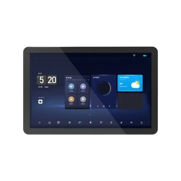 10.1-inch ESP32P4 development board supports Xiaozhi ESP32 C6 capacitive touch screen H3CA Multimedia Control Board Expandable Storage and Port
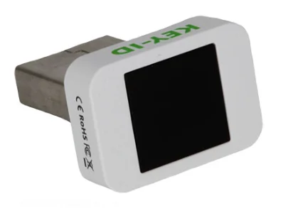 Key-id Hello + FIDO2 fingerprint USB security key Identifies the fingerprint ESP32
$38.90
Key-id Hello + FIDO2 fingerprint USB security key Identifies the fingerprint ESP32
$38.90
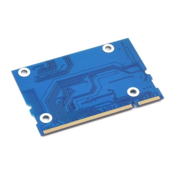 CM4-to-CM3-Board, Raspberry Pi CM4 To CM3 Adapter, Alternative Solution for Raspberry Pi CM3 / CM3+
$16.50
CM4-to-CM3-Board, Raspberry Pi CM4 To CM3 Adapter, Alternative Solution for Raspberry Pi CM3 / CM3+
$16.50
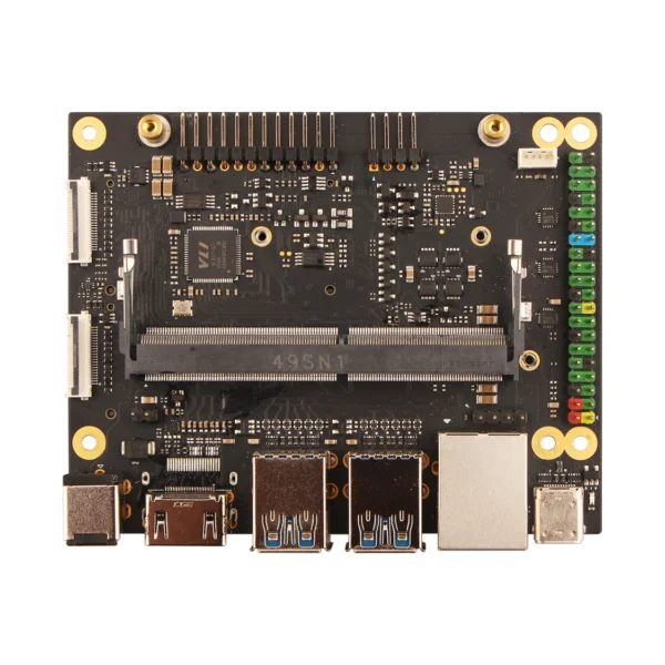 Radxa NX4 IO Board — An Application Board for Radxa NX4
$98.90
Radxa NX4 IO Board — An Application Board for Radxa NX4
$98.90
 Stock PXDNGL01TOBO1 EVAL DONGLE USB password lock PX-DNGL
$258.90
Stock PXDNGL01TOBO1 EVAL DONGLE USB password lock PX-DNGL
$258.90
EMC testing is expensive, and failing it is worse than the test fee — it costs you a respin, a
When a battery-powered product dies too soon, the instinct is to blame the firmware. Surely there is a sleep mode
A wearable PCB is not just a small PCB. It is a board where every constraint that normally has some
The STM32 family is the workhorse of embedded hardware, and almost every project that uses one starts the same way:
The nRF52840 is one of the most popular BLE and multiprotocol chips in the world, and for good reason: it
The ESP32-C6 looks, at first glance, like a small update to the ESP32 family. It has more radios, a newer
No account yet?
Create an Account