If you are searching for "what is a rigid PCB", you probably already know the textbook definition: it is a printed circuit board built on a solid, non-flexible substrate. But if you are a hardware engineer, a product designer, or a procurement manager, a basic definition won't help you avoid a costly manufacturing failure.
The reality in the electronics industry is that a rigid PCB design might pass bench testing flawlessly in a 5-piece prototype run, only to suffer massive yield drops or field failures during mass production. When this happens, the root cause is rarely the schematic itself. It almost always traces back to overlooked Design for Manufacturability (DFM) constraints, incorrect laminate specifications, or a fragmented supply chain.
This guide bypasses the basic encyclopedia definitions. We are going to break down the critical material specifications, hidden sourcing pitfalls, and actionable DFM rules you need to ensure your custom rigid PCB fabrication and assembly succeed on the first production run.
What Exactly Is a Rigid PCB? (Core Structure & Materials)
A rigid printed circuit board (rigid PCB) is constructed on a solid substrate material that provides absolute mechanical support and dimensional stability. Unlike flexible circuits that use polyimide to allow bending, rigid PCBs typically utilize fiberglass-reinforced epoxy laminate (most commonly FR-4).
Electronic components are soldered onto copper traces that are chemically etched onto this substrate. The inherent stiffness of the board ensures that solder joints remain intact under mechanical vibration, shock, and thermal expansion. This makes rigid PCBs the default, most cost-effective choice for applications where long-term structural integrity and high component density are non-negotiable.
To understand how a rigid PCB performs, you need to look at its physical anatomy:
- Substrate Layer (Base Laminate): The foundation of the board. Standard FR-4 provides rigidity, but for high-thermal or RF applications, specialized materials like High-Tg FR-4, Rogers, or Aluminum cores are used.
- Copper Layer: Laminated onto the substrate. Rigid PCBs can be single-sided, double-sided, or multilayer. Copper thickness is measured in ounces per square foot (oz/ft²), directly impacting current-carrying capacity and impedance.
- Solder Mask Layer: The green (or other colored) insulating layer over the copper. It prevents accidental short circuits and protects the traces from oxidation.
- Silkscreen Layer: The printed text and symbols used for component identification, testing points, and assembly guidance.
- Surface Finish: The exposed copper treatment (e.g., ENIG, HASL, OSP, Immersion Silver) that ensures solderability and prevents pad degradation over time.
Rigid PCB vs. Flexible PCB: A Decision Matrix for Engineers
A common bottleneck during the design phase is deciding between rigid and flexible architectures. This decision should be driven by mechanical requirements, environmental conditions, and budget, not just industry trends.
The Engineering Verdict: Choose rigid PCBs when your application demands high component density, superior heat dissipation, strict impedance control, or the lowest possible unit cost at scale. Reserve flexible or rigid-flex PCBs strictly for applications where the board must bend or fold to fit the enclosure (e.g., wearable tech, camera modules, or dynamic hinges).
Types of Rigid PCBs and Their Real-World Manufacturing Constraints
Rigid PCBs are not a "one-size-fits-all" category. Specifying the right type is critical for your application's success.
- Single-Sided & Double-Sided PCBs: The workhorses of low-complexity electronics (lighting, basic power supplies, consumer appliances). Double-sided boards utilize plated through-holes (PTH) to connect both sides, supporting both SMT and through-hole components.
- Multilayer PCBs: Stacks of 3 or more conductive layers separated by insulating prepreg. They are mandatory for high-speed digital, computing, and complex IoT devices. Manufacturing constraint: Lamination cycle times and via registration become critical past 10 layers.
- Heavy Copper PCBs: Utilizing 3oz to 20oz copper traces. Essential for power distribution and motor controllers. Manufacturing constraint: Requires specialized etching compensation to maintain trace spacing and prevent undercutting.
- High-Tg PCBs: Built with materials that have a Glass Transition Temperature (Tg) of 170°C or higher. Mandatory for automotive and industrial environments.
- High-Frequency PCBs: Utilizing low-loss laminates (Rogers, Teflon) for RF and microwave applications. Manufacturing constraint: Requires strict impedance control and specialized drilling parameters.
- Metal Core PCBs (MCPCB): Featuring an aluminum or copper base for maximum thermal dissipation, primarily used in LED lighting and power electronics.
3 Hidden Pitfalls in Rigid PCB Sourcing (And How to Avoid Them)
Sourcing custom rigid PCBs introduces specific risks that generic online quote engines fail to address. Based on years of resolving manufacturing bottlenecks, here are the most common failure points and how to engineer around them.
Pitfall 1: The "All FR-4 is Identical" Assumption
Designers frequently specify generic "FR-4" without realizing that material properties vary drastically. Standard FR-4 has a Tg of around 130°C–140°C. If your rigid PCB undergoes multiple lead-free reflow cycles (which peak around 260°C), standard FR-4 will soften. This causes Z-axis expansion, leading to plated through-hole (PTH) barrel cracking and catastrophic failure.
Our Fix: For multi-layer boards or high-thermal applications, explicitly specify Mid-Tg (150°C–160°C) or High-Tg (≥170°C) materials, such as Isola 370HR or Shengyi S1000-2.
Pitfall 2: The Prototype-to-Production Scalability Gap
A 5-piece prototype built with manual processes or premium, readily available material batches may not translate to a 5,000-unit production run. Minor DFM violations that were ignored during prototyping become massive yield killers at scale.
Our Fix: Bridge the gap early. Utilizing a turnkey rigid PCB prototype and assembly manufacturing service ensures that the DFM feedback provided during your prototyping phase is directly informed by mass-production capabilities. This prevents costly "re-engineering" shocks when scaling.
Pitfall 3: Fragmented Supply Chain Accountability
Sourcing bare boards from one vendor, components from a global distributor, and assembly from a third-party house creates logistical friction. If a board fails in the field, the bare board fabricator will blame the assembler, and the assembler will blame the component batch.
Our Fix: Consolidate accountability. A true turnkey manufacturer assumes ownership of the entire process. If you are preparing to scale your product line, initiating an OEM/ODM bulk manufacturing inquiry early in your design cycle allows the engineering team to align your design with the most cost-effective and scalable production methodologies from day one.
The Non-Negotiable DFM Checklist for Rigid PCB Fabrication
To guarantee a high first-pass yield, your Gerber and drill files must be optimized for fabrication. Verify these critical parameters before releasing your design to the factory floor:
- Impedance Control Stack-up: Do not guess your stack-up. Collaborate with your manufacturer’s CAM (Computer-Aided Manufacturing) team to define the exact copper weight, prepreg thickness, and core material required to achieve your target impedance (e.g., 50Ω single-ended, 100Ω differential).
- Annular Ring and Hole Tolerance: Ensure plated through-holes maintain a minimum annular ring of 0.15mm (6 mil) to prevent breakout during mechanical drilling. Clearly distinguish between plated (PTH) and non-plated (NPTH) holes in your drill file.
- Solder Mask and Silkscreen Clarity: Maintain a minimum solder mask dam of 0.1mm (4 mil) between fine-pitch pads to prevent solder bridging. Keep silkscreen text at least 0.15mm (6 mil) in height for legibility after assembly.
- Thermal Relief for Ground Planes: When connecting vias or pads to large copper pours, use thermal relief spokes. Without them, the copper plane acts as a heat sink, causing cold solder joints or component tombstoning during reflow.
- Panelization Strategy: For irregularly shaped rigid PCBs, discuss panelization (V-score or tab-routing with mouse bites) early. Proper panelization maximizes material utilization and ensures smooth depanelization without inducing mechanical stress on edge-mounted components.
Frequently Asked Questions
Q: What is the practical maximum number of layers for a rigid PCB?
A: While standard rigid PCBs typically range from 1 to 12 layers, advanced manufacturing techniques can produce rigid PCBs with up to 40+ layers for enterprise servers and advanced networking equipment. However, designs exceeding 16 layers require careful DFM review to manage lamination cycle times and via-in-pad filling.
Q: How do I choose between standard FR-4 and High-Tg FR-4?
A: If your board will undergo multiple lead-free reflow cycles (peaking around 260°C), or if the end-use environment consistently exceeds 125°C, you must specify High-Tg (≥170°C) material. For standard consumer electronics, standard FR-4 is adequate and more cost-effective.
Q: What surface finish is best for rigid PCBs with fine-pitch components?
A: For fine-pitch components (such as BGAs or QFNs), ENIG (Electroless Nickel Immersion Gold) or ENEPIG is highly recommended. They provide a flat, coplanar surface that ensures reliable soldering. HASL is generally avoided for fine-pitch designs due to its uneven surface topology.
Q: Can a rigid PCB manufacturer handle the full component assembly (PCBA)?
A: Yes. Opting for a turnkey rigid PCB assembly service means the manufacturer handles bare board fabrication, component sourcing, SMT/through-hole assembly, and functional testing. This single-point accountability drastically reduces lead times and eliminates quality disputes.
Secure Your Production with Precision Manufacturing
Understanding "what is a rigid PCB" is just the starting point. The true measure of success lies in material selection, strict DFM enforcement, and partnering with a manufacturer that demonstrates verifiable engineering expertise. By addressing these factors proactively, you eliminate costly respins and accelerate your time-to-market.
Do not leave your hardware’s reliability to chance. Whether you require a rapid prototype to validate your design or a scalable, turnkey solution for high-volume production, our engineering team is prepared to provide actionable DFM feedback and precision manufacturing.

 eXtremeRate Replacement Handheld Controller Housing Custom Shell with Screen Protector & ABXY Buttons for Nintendo Switch Lite
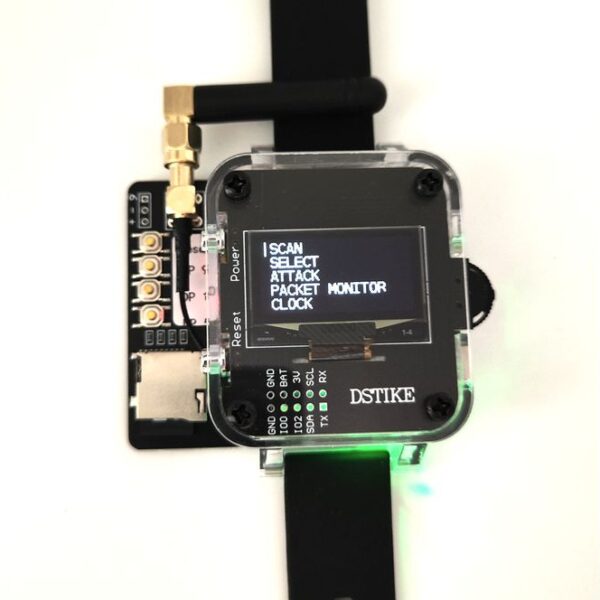 Deauther Watch Z | 2.4G Wi-Fi+HID Attack TESTING
$53.90
Deauther Watch Z | 2.4G Wi-Fi+HID Attack TESTING
$53.90
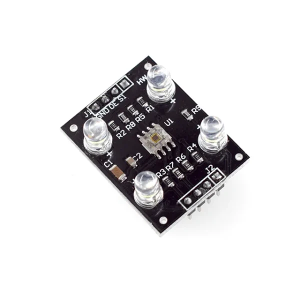 Color Recognition Sensor TCS230 TCS3200 Color Sensor Module Accessories For MCU DIY DC 3-5V Input
$4.90
Color Recognition Sensor TCS230 TCS3200 Color Sensor Module Accessories For MCU DIY DC 3-5V Input
$4.90
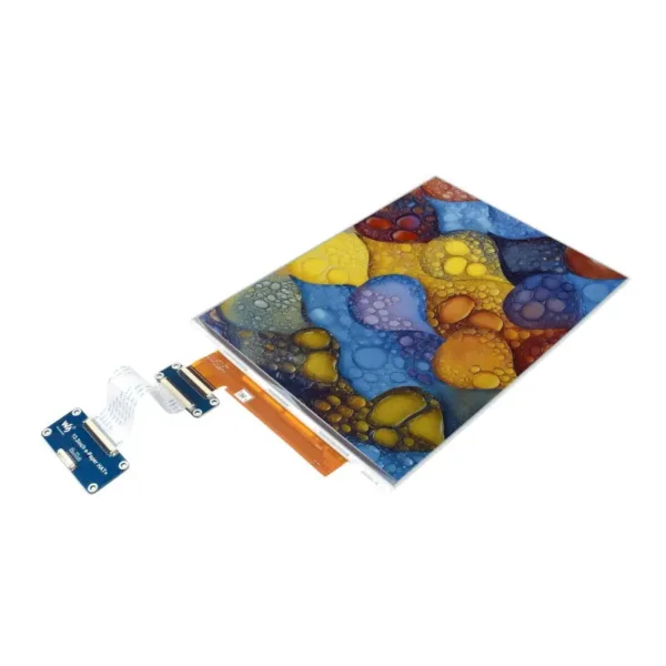 13.3inch E Ink Spectra 6 (E6) Full Color E-Paper Display 1600x1200 Pixels Ideal for Price Tags And Shelf Labels
 LILYGO T-Deck Plus 433MHz 868MHz 915MHz ESP32-S3 Development Board GPS Long Range Communication Module with External Antenna
$86.90
LILYGO T-Deck Plus 433MHz 868MHz 915MHz ESP32-S3 Development Board GPS Long Range Communication Module with External Antenna
$86.90