Why Castellated Holes Are Critical for Modern Modular Design
In modern electronics, the trend is unequivocally moving toward modularity. Instead of designing a monolithic, single-board solution, engineers increasingly design a "carrier" or "mother" board and integrate pre-certified, pre-tested sub-modules (such as wireless communication, power management, or processing units).
Castellated holes are the mechanical and electrical bridge that makes this possible. By plating the walls of drilled holes and then routing the PCB edge directly through the center of these holes, manufacturers create a series of semi-circular, plated pads along the board's perimeter.
When this module is placed on a carrier board, these half-holes align with corresponding surface pads. During the reflow soldering process, solder paste melts and flows up into the half-hole, creating a robust, visible, and easily inspectable solder fillet. This provides superior mechanical strength and electrical conductivity compared to traditional edge connectors or manual wire soldering.
However, creating reliable castellated holes is one of the most challenging processes in PCB fabrication and assembly. It requires a precise intersection of drilling, plating, routing, and SMT processes.
Top 3 Castellated Hole Manufacturing Pain Points (And How We Solve Them)
As a hardware developer, your goal is a high first-pass yield. Castellated holes introduce unique vulnerabilities. Here is how a professional manufacturing partner mitigates these risks:
1. Plating Detachment and "Copper Pull" During Routing
The Pain Point: The most common failure in castellated holes occurs during the final CNC routing (breakout) process. If the router bit pulls against the plating, it can tear the copper barrel away from the inner pad, leaving a disconnected or fractured half-hole. This results in open circuits or high-resistance joints.
Our Solution: We utilize a specialized two-step routing process. First, we route the inner portion of the castellated hole with a smaller diameter bit to relieve stress. Then, we use a precision, sharp carbide router bit for the final edge breakout, moving in a direction that pushes the copper into the substrate rather than pulling it out. Additionally, we ensure the hole-to-pad ratio is optimized to maximize copper adhesion.
2. Solder Wicking and Insufficient Fillet Formation
The Pain Point: During SMT assembly on the carrier board, capillary action can draw too much solder paste up into the castellated hole (wicking), leaving insufficient solder on the surface pad to form a reliable fillet. Conversely, if the hole is too small, solder cannot flow in at all, resulting in a weak mechanical bond.
Our Solution: We engineer the module’s footprint with extended pads. The copper pad extends slightly beyond the edge of the board (typically by 0.25mm to 0.3mm). This provides a dedicated "solder reservoir" that guarantees enough volume to form a concave, IPC-compliant solder fillet, even if some wicking occurs. We also provide specific stencil aperture recommendations for the carrier board to compensate for this volume.
3. Solder Mask Slivers and Burr-Induced Shorts
The Pain Point: If the solder mask opening is too close to the routed edge, the routing process can tear the mask, creating loose "slivers" of mask material or copper burrs. These burrs can bridge adjacent castellated holes, causing catastrophic short circuits when the module is mounted.
Our Solution: We enforce strict solder mask clearance rules (minimum 0.15mm to 0.2mm from the hole edge to the mask opening). Our CAM (Computer-Aided Manufacturing) engineers automatically flag and adjust any designs that risk mask slivers. Furthermore, we employ post-routing brushing and micro-etching processes to guarantee all edges are completely free of conductive burrs.
The Ultimate DFM Checklist for Castellated Holes
To ensure your design is 100% manufacturable, your CAD layout must adhere to these industry-proven DFM (Design for Manufacturability) rules. Note: These are general best practices; always confirm with your specific manufacturer’s capabilities.
- Hole Diameter: The finished plated hole diameter should be ≥ 0.6mm (24 mil). Holes smaller than this are highly prone to plating rupture during routing. (0.8mm is the recommended sweet spot for optimal reliability).
- Pad Size: The outer copper pad should be at least 0.25mm to 0.3mm larger than the hole diameter on all sides. For a 0.8mm hole, a 1.3mm to 1.4mm pad is ideal.
- Pad Extension (Overhang): The pad must extend beyond the final board edge by at least 0.25mm. This is non-negotiable for proper solder fillet formation on the carrier board.
- Solder Mask Clearance: The solder mask opening must be 0.15mm to 0.2mm larger than the copper pad to prevent mask tearing during the routing breakout.
- Number of Castellations: For a standard module, a minimum of 3 to 4 castellated holes per side is recommended to ensure adequate mechanical stability and alignment during the SMT pick-and-place process.
- Spacing Between Holes: Maintain a minimum edge-to-edge distance of 0.5mm to 0.8mm between adjacent castellated holes to prevent the router bit from weakening the board structure or causing shorts.
The Assembly Challenge: Why Turnkey Expertise Matters
Designing the castellated module is only half the battle. The real test of reliability happens during the SMT assembly of the module onto the carrier board.
Mounting castellated modules requires precise coordination:
- Stencil Design: The solder paste stencil for the carrier board must be carefully calculated. Often, the aperture on the carrier board needs to be slightly larger or printed with a stepped stencil to ensure enough solder volume is present to fill the half-hole and form a visible fillet.
- Pick-and-Place Accuracy: The module must be placed with high precision. If the module shifts, the half-holes will misalign with the carrier pads, leading to open joints or solder bridging.
- Reflow Profiling: The thermal profile must be optimized to allow the solder to flow freely into the castellated holes without causing the module to "float" or shift due to uneven surface tension.
This is precisely why sourcing bare boards from one vendor and assembly from another often leads to finger-pointing when defects occur. You need a unified, accountable partner.
Why Partner with a Professional Castellated PCB & Assembly Manufacturer?
Sourcing castellated PCBs is not a commodity purchase; it requires a manufacturer with proven expertise in both advanced fabrication and complex assembly.
We bridge the gap between modular design concepts and high-yield manufacturing reality. Our end-to-end capabilities ensure your project succeeds at every stage:
- Proactive DFM for Modular Designs: Before production begins, our engineering team reviews your module and carrier board files. We verify hole sizes, pad extensions, and solder mask clearances, providing you with a detailed, free DFM report to eliminate routing and soldering risks before they happen.
- Seamless Prototyping to Turnkey Assembly: We don’t just fabricate the castellated module; we assemble the entire system. Our turnkey PCB assembly manufacturing service handles the complex logistics of sourcing the module components, designing the optimal carrier board stencil, executing precise pick-and-place alignment, and validating the solder fillets with X-ray and AOI inspection. Discover how we simplify your workflow: PCB Prototype & Turnkey PCB Assembly Manufacturing.
- Scalable OEM/ODM Bulk Production: When your modular design is validated, scaling to mass production requires unwavering consistency. We utilize automated optical inspection (AOI) specifically calibrated to check castellated hole solder fillets, ensuring every single unit meets strict IPC-A-610 Class 2/3 standards. Request a detailed, competitive quote for your next large-scale project: OEM/ODM Bulk Inquiry.
Frequently Asked Questions (FAQ)
Q1: Can castellated holes be used on flexible PCBs (FPC)?
A: While technically possible, it is highly discouraged. The mechanical stress of routing half-holes on a flexible substrate almost guarantees tearing of the copper and polyimide layers. Castellations are best suited for rigid or rigid-flex PCBs where the rigid section contains the holes.
Q2: What is the minimum finished hole size you recommend for castellations?
A: We strongly recommend a minimum finished hole diameter of 0.6mm (24 mil), with 0.8mm (32 mil) being the optimal size for balancing board space and plating reliability during the routing breakout process.
Q3: Do you provide assembly services for the carrier board that receives the castellated module?
A: Yes. We offer complete turnkey assembly for both the module itself and the carrier board it mounts to. This ensures we control the entire process, from stencil design and paste volume optimization to reflow profiling, guaranteeing perfect solder fillets.
Q4: How do you inspect the quality of solder joints on castellated holes?
A: Because the solder fillet is formed on the side of the board, standard top-down AOI can sometimes miss defects. We utilize angled AOI cameras and, for critical applications, 3D X-ray inspection to verify that the solder has properly wicked into the half-hole and formed a reliable, void-free joint.
Precision Engineering for Modular Success
Castellated holes are a powerful design feature that enables compact, modular, and highly maintainable electronic products. However, their unique geometry makes them highly susceptible to fabrication and assembly defects if DFM rules are ignored.
Don’t leave your product’s reliability to chance or manufacturers who lack specialized routing and assembly capabilities. By partnering with a team that understands the intricate relationship between hole plating, edge routing, and SMT solder dynamics, you transform a potential manufacturing bottleneck into a seamless, scalable advantage.

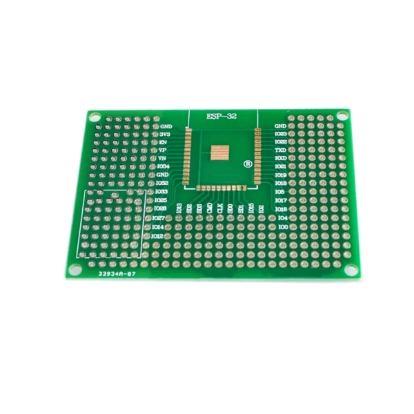 wifi ESP8266/ Prototype PCB ESP12F12E/ESP32 Cavity Board/ 5X7 Double Side Tin Plated
$2.90
wifi ESP8266/ Prototype PCB ESP12F12E/ESP32 Cavity Board/ 5X7 Double Side Tin Plated
$2.90
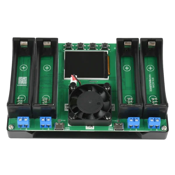 18650 Lithium Battery Capacity Tester
$10.90
18650 Lithium Battery Capacity Tester
$10.90
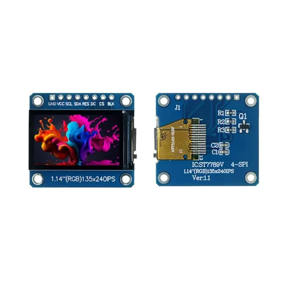 1.14 Inch TFT LCD Display ST7789 SPI Interface 135x240 Resolution Color Screen - Narrow Bar Type Small Screen Module
 Smart Fingerbot - Bluetooth Button Pusher for Voice & App Control (Works with Alexa & Google Home)
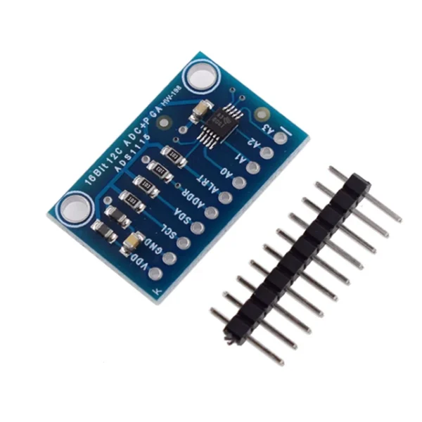 16 Bit I2C ADS1115 Module ADC 4 Channel with Pro Gain Amplifier
$3.30
16 Bit I2C ADS1115 Module ADC 4 Channel with Pro Gain Amplifier
$3.30