
EMC/EMI Checklist Before Your Board Goes to Certification
EMC testing is expensive, and failing it is worse than the test fee — it costs you a respin, a
The 0.96-inch OLED display based on the SSD1306 driver is a favorite among IoT hobbyists for its crisp visibility, low power consumption, and ease of use. When paired with the versatile ESP8266, it becomes a powerful tool for creating standalone data dashboards, sensor readouts, or smart device interfaces.
This comprehensive tutorial goes beyond basic "Hello World" examples. You’ll learn how to set up the hardware, install the necessary libraries, display text and graphics, and integrate the display into practical projects—all within the familiar Arduino IDE.
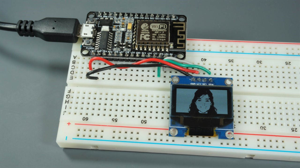
The SSD1306 OLED is a monochrome, 128x64 pixel display. Its key advantages make it ideal for ESP8266 projects:
No Backlight Required: Unlike LCDs, OLEDs are self-emissive, offering perfect black levels and high contrast, especially in low-light conditions.
Low Power Consumption: Pixels only draw power when they are on, making it excellent for battery-powered ESP8266 projects.
Communication Protocols: Commonly available in I2C (4-pin) or SPI (6-7 pin) variants. The I2C version is simpler, using only two data pins, and is the focus of this guide.
The I2C connection is straightforward. You only need four wires. It’s critical to connect the display's VCC to the ESP8266's 3.3V pin, as 5V will likely damage it.
Here is the standard wiring table:
| OLED Display Pin | ESP8266 GPIO Pin (NodeMCU/D1 Mini) | ESP8266 Physical Pin |
|---|---|---|
| VCC | 3.3V | 3.3V Power Pin |
| GND | GND | Ground Pin |
| SCL (Clock) | GPIO 5 (D1) | Digital Pin D1 |
| SDA (Data) | GPIO 4 (D2) | Digital Pin D2 |
Why GPIO 4 and 5? On most ESP8266 boards, these pins are the default I2C pins and are not used by other critical functions like bootstrapping or SPI flash, ensuring stable communication.
Quick Troubleshooting Tip: If the display doesn’t light up, first double-check the I2C address. While the default is 0x3C, some modules use 0x3D. Use a simple I2C scanner sketch to confirm.
Before writing code, you need two core libraries from Adafruit:
Adafruit SSD1306: The hardware-specific driver for the OLED.
Adafruit GFX: A core graphics library that handles shapes, text, and fonts.
Installation Steps:
Open Arduino IDE.
Navigate to Sketch > Include Library > Manage Libraries....
In the Library Manager, search for “Adafruit SSD1306” and install it.
Next, search for “Adafruit GFX” and install it.
Ensure you have the ESP8266 board package installed. If not, add it via File > Preferences by entering http://arduino.esp8266.com/stable/package_esp8266com_index.json into the "Additional Boards Manager URLs" field, then install from Tools > Board > Boards Manager.
The quickest way to verify your setup is to run a library example.
Go to File > Examples > Adafruit SSD1306.
Select the example matching your display size and connection (e.g., ssd1306_128x64_i2c).
Before uploading, ensure you have:
Selected your ESP8266 board (e.g., NodeMCU 1.0) under Tools > Board.
Selected the correct COM port under Tools > Port.
Upload the sketch. You should see a sequence of graphics and animations on your display, confirming everything works.
Let’s break down the essential functions to control the display.
Initialization:
#include <Wire.h>
#include <Adafruit_GFX.h>
#include <Adafruit_SSD1306.h>

#define SCREEN_WIDTH 128
#define SCREEN_HEIGHT 64
#define OLED_RESET -1 // If your display has a reset pin, define its GPIO here

Adafruit_SSD1306 display(SCREEN_WIDTH, SCREEN_HEIGHT, &Wire, OLED_RESET);

void setup() {
  // Initialize with I2C address 0x3C
  if(!display.begin(SSD1306_SWITCHCAPVCC, 0x3C)) {
    Serial.println(F("SSD1306 allocation failed"));
    for(;;); // Halt forever on failure
  }
  display.display(); // Show the Adafruit splash screen
  delay(2000);
  display.clearDisplay(); // Clear the buffer for new drawings
}
Basic Text Display:
void displayText() {
  display.clearDisplay();

  display.setTextSize(1);        // Normal 1:1 pixel scale (6x8px font)
  display.setTextColor(SSD1306_WHITE); // Draw white text
  display.setCursor(0, 0);       // Top-left corner
  display.println("Hello, World!");

  display.setTextSize(2);
  display.setCursor(0, 20);
  display.println("2X Size");

  display.setTextColor(SSD1306_BLACK, SSD1306_WHITE); // Inverse text
  display.setCursor(0, 45);
  display.println(" Inverse ");

  display.display(); // This command MUST be called to make changes visible
}
Drawing Shapes:
The Adafruit GFX library provides simple functions for drawing:
void drawShapes() {
  display.clearDisplay();
  // Draw a rectangle (x, y, width, height, color)
  display.drawRect(10, 10, 50, 30, SSD1306_WHITE);
  // Fill a circle (centerX, centerY, radius, color)
  display.fillCircle(90, 25, 15, SSD1306_WHITE);
  // Draw a line (x1, y1, x2, y2, color)
  display.drawLine(0, 0, 127, 63, SSD1306_WHITE);
  display.display();
}
Once you master the basics, integrate the OLED into real applications:
IoT Sensor Dashboard: Connect a DHT11/DHT22 sensor and display real-time temperature and humidity readings.
Wi-Fi Signal Strength Meter: Use WiFi.RSSI() to get the signal strength and display it as a number or a visual bar graph.
Clock with NTP: Synchronize time via Network Time Protocol (NTP) and create a sleek digital clock that updates automatically.
API Data Display: Have your ESP8266 fetch data from a public API (like weather or cryptocurrency prices) and show it on the screen.
Example Snippet for Sensor Data:
// After reading from a sensor (e.g., temperature)
float temp = readTemperature();
display.clearDisplay();
display.setTextSize(1);
display.setCursor(0,0);
display.print("Temperature:");
display.setTextSize(2);
display.setCursor(0, 20);
display.print(temp);
display.print(" C");
display.display();
Memory Constraints: The ESP8266 has limited RAM. Use F() macro to store constant strings in program memory (Flash) instead of RAM: display.println(F("Static Text"));
Avoid delay() in Animations: For smooth animations or updating sensor data, use millis() for non-blocking timing to keep the ESP8266 responsive.
Display is Blank or Garbled?
Verify all connections, especially GND.
Confirm the I2C address with a scanner sketch.
Ensure the correct display.begin(...) address is used in your code.
Check that display.display() is being called after your drawing commands.
The combination of ESP8266 and the SSD1306 OLED opens a world of possibilities for creating interactive, informative projects with a professional look. Start with the basics, experiment with the graphics library, and soon you’ll be building custom interfaces for all your IoT gadgets.
Feel free to share your creations or ask specific questions in the comments below! What will you display on your OLED screen first?
======================================
No account yet?
Create an Account