
EMC/EMI Checklist Before Your Board Goes to Certification
EMC testing is expensive, and failing it is worse than the test fee — it costs you a respin, a
UART (Universal Asynchronous Receiver/Transmitter) is the foundational serial protocol for the ESP32, enabling communication with computers, sensors, GPS modules, and other microcontrollers. Unlike synchronous protocols like SPI and I2C, UART operates asynchronously, relying on a pre-agreed baud rate for timing, making it versatile and widely supported. This comprehensive guide, updated for 2026, delves deep into ESP32 UART, from basic principles to advanced multi-board communication, complete with ready-to-use Arduino IDE code.
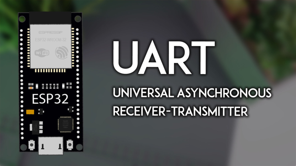
The ESP32 chip is equipped with three independent UART peripherals (UART0, UART1, and UART2), providing flexible options for various serial communication tasks. Each UART requires only three connections: TX (Transmit), RX (Receive), and a shared GND (Ground). Data is sent bit-by-bit, making it simple and reliable for many embedded applications.
A critical point is the default pin mapping, which varies by ESP32 model and can be reconfigured in software. For standard ESP32 boards (like the ESP32 DevKit V1), the defaults are:
UART0: GPIO 1 (TX), GPIO 3 (RX). Typically used for Serial Monitor and programming.
UART1: GPIO 10 (TX), GPIO 9 (RX). Often unusable in default state as these pins connect to flash memory.
UART2: GPIO 17 (TX), GPIO 16 (RX). Usually free for general use.
⚠️ Important Note for ESP32-S3 Users: The pinout differs significantly. UART0 is fixed to GPIO 43/44, while UART1 and UART2 offer full flexibility. Always consult your board's pinout diagram.
The most common starting point is communicating with your computer via the Arduino IDE's Serial Monitor. This uses UART0 over the board's USB connection.
Upload this basic echo sketch to establish two-way communication:
String receivedMessage = "";

void setup() {
  // Initialize UART0 for Serial Monitor at 115200 baud
  Serial.begin(115200);
  Serial.println("ESP32 Ready. Type a message:");
}

void loop() {
  while (Serial.available()) {
    char c = Serial.read();
    if (c == '\n') { // Check for Enter key (newline)
      Serial.print("Echo: ");
      Serial.println(receivedMessage);
      receivedMessage = ""; // Clear for next message
    } else {
      receivedMessage += c; // Build the message
    }
  }
}
Upload and Test: Open the Serial Monitor (set to 115200 baud), type a message, and press Enter. The ESP32 will echo it back. This confirms your UART0 is functioning correctly.
You are not limited to default pins. The HardwareSerial library allows you to assign UART functions to almost any GPIO pin. This is essential for using UART1 or creating multiple serial ports.
// Define your custom RX and TX pins
#define CUSTOM_RX_PIN 16
#define CUSTOM_TX_PIN 17

// Create a serial object on UART2
HardwareSerial mySerial(2);

void setup() {
  Serial.begin(115200); // Keep UART0 for debugging

  // Initialize custom UART2 at 9600 baud, 8N1 frame format
  mySerial.begin(9600, SERIAL_8N1, CUSTOM_RX_PIN, CUSTOM_TX_PIN);
  Serial.println("Custom UART2 Initialized.");
}

void loop() {
  // Your code using mySerial.read() and mySerial.print() here
}
Key Parameters in begin():
Baud Rate: Speed (e.g., 9600, 115200). Devices must match.
Frame Format: SERIAL_8N1 (8 data bits, No parity, 1 stop bit) is standard.
RX & TX Pins: Your chosen GPIOs.
A common real-world use for UART is reading data from modules like the NEO-6M GPS. Connect the GPS's TX to your ESP32's RX pin (e.g., GPIO 16) and the GPS's RX to the ESP32's TX pin (e.g., GPIO 17).
#define GPS_RX 16
#define GPS_TX 17
#define GPS_BAUD 9600 // Standard NEO-6M baud rate

HardwareSerial gpsSerial(2); // Use UART2

void setup() {
  Serial.begin(115200);
  gpsSerial.begin(GPS_BAUD, SERIAL_8N1, GPS_RX, GPS_TX);
}

void loop() {
  // Read and forward GPS data to Serial Monitor
  while (gpsSerial.available()) {
    char gpsData = gpsSerial.read();
    Serial.write(gpsData); // Stream NMEA sentences
  }
  delay(500);
}
This sketch reads the raw NMEA sentences from the GPS and displays them on the Serial Monitor for parsing.
You can create a network of ESP32s using UART. One board acts as a Sender, another as a Receiver.
1. Wiring the Boards:
Connect Sender TX -> Receiver RX
Connect Sender RX -> Receiver TX
Connect GND -> GND (This is mandatory)
2. Sender Code (Transmits a counter):
#define TX_PIN 19
#define RX_PIN 21
HardwareSerial dataSerial(1); // Use UART1
int counter = 0;

void setup() {
  Serial.begin(115200);
  dataSerial.begin(9600, SERIAL_8N1, RX_PIN, TX_PIN);
}

void loop() {
  dataSerial.println(counter); // Send number
  Serial.println("Sent: " + String(counter));
  counter++;
  delay(1000);
}
3. Receiver Code (Reads the incoming data):
#define RX_PIN 21 // Connects to Sender's TX
#define TX_PIN 19 // Connects to Sender's RX
HardwareSerial dataSerial(1);

void setup() {
  Serial.begin(115200);
  dataSerial.begin(9600, SERIAL_8N1, RX_PIN, TX_PIN);
}

void loop() {
  if (dataSerial.available()) {
    String received = dataSerial.readStringUntil('\n');
    Serial.println("Received: " + received);
  }
}
After uploading the respective codes, open the Serial Monitor for the Receiver board to see the incrementing numbers sent from the Sender.
Even with correct code, hardware issues can arise. Here are solutions to frequent problems:
| Problem | Likely Cause | Solution |
|---|---|---|
| No data in Serial Monitor | Wrong baud rate or port. | Ensure the Serial Monitor baud rate matches the Serial.begin() rate in code. Select the correct COM/Port. |
| Garbage/random characters | Baud rate mismatch between devices. | Verify and set identical baud rates on both the ESP32 code and the connected device (GPS, other MCU). |
failed to connect to ESP32 |
Serial port is busy. | Close the Serial Monitor before uploading new code. |
| ESP32-S3 not working | Incorrect pin assignment. | Use the correct fixed pins for UART0 (GPIO 43, 44) on ESP32-S3. |
Pro Tip: For stable communication over longer distances or in noisy environments, consider using RS-485 transceiver chips with your ESP32's UART.
Buffer Management: For high-speed data, implement ring buffers to prevent data loss in the loop().
Parsing Serial Data: Use readStringUntil() or state machines to reliably parse complex messages (like NMEA sentences).
Power Saving: You can disable UART peripherals with mySerial.end() when not in use to reduce power consumption.
Interrupts: While the HardwareSerial library uses interrupts internally, for custom protocols you can attach ISRs directly to GPIO pins.
UART remains one of the most straightforward and effective ways to connect your ESP32 to the world. By mastering default configurations, custom pin mapping, and practical applications like GPS interfacing and board-to-board communication, you unlock a vast range of project possibilities.
======================================

No account yet?
Create an Account