
EMC/EMI Checklist Before Your Board Goes to Certification
EMC testing is expensive, and failing it is worse than the test fee — it costs you a respin, a
Navigating the ESP32's 48-pin array can be daunting. With multiple functions per pin, bootloader quirks, and limitations on certain GPIOs, selecting the right pin for your project is critical. This definitive guide cuts through the complexity, offering a clear, actionable reference for beginners and seasoned developers alike. We'll explore not just what each pin does, but how and when to use it, helping you avoid common pitfalls and build more reliable ESP32-based systems.
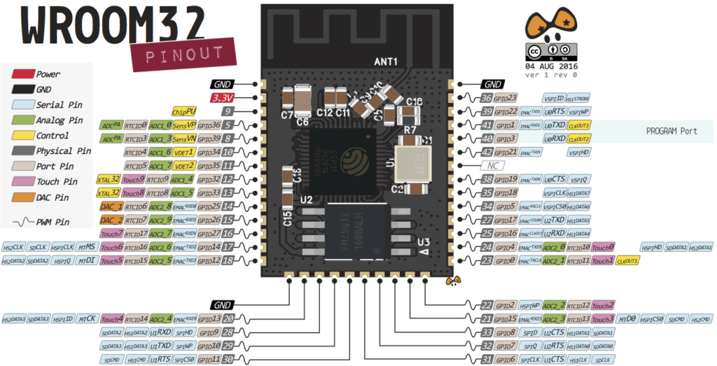
Before diving into specifics, here's what you need to know to avoid damaging your board or encountering erratic behavior. The ESP32's flexibility comes with caveats, especially during the boot process.
Strapping Pins (Critical for Boot Mode): These pins (GPIO 0, 2, 4, 5, 12, 15) are read at boot to determine operational mode (e.g., flashing vs. normal run). Incorrect voltages can prevent your board from starting.
GPIO 0: Must be LOW to enter bootloader/flashing mode.
GPIO 2: Must be floating or LOW during boot.
GPIO 12 & 15: Must be LOW and HIGH during boot, respectively.
Pins with Boot-Time Activity: Some pins output signals or go HIGH during boot/reset, which can inadvertently activate connected components (like LEDs or motors).
GPIO 1 & 3: Default UART0 TX/RX for Serial Monitor; have boot debug output.
GPIO 6-11: Connected to internal SPI flash memory. Using these can corrupt the filesystem and crash the chip. Avoid them entirely.
GPIO 14 & 15: Output PWM signals at boot.
Input-Only Pins: GPIOs 34, 35, 36, and 39 are input-only (GPI). They lack internal pull-up/pull-down resistors and cannot be used for output functions like PWM or driving LEDs.
The table below provides an at-a-glance safety rating for each GPIO, incorporating these critical behaviors.
| GPIO | Input | Output | Safety & Usage Notes |
|---|---|---|---|
| 0 | Pulled Up | OK | Strapping Pin. Outputs PWM at boot. Must be LOW to enter flash mode. |
| 1 | TX Pin | OK | Boot debug output (HIGH). Default UART0 TX. |
| 2 | OK | OK | Strapping Pin. Often connected to onboard LED. Must be floating/LOW for flash. |
| 3 | OK | RX Pin | HIGH at boot. Default UART0 RX. |
| 4 | OK | OK | Strapping Pin. Also capacitive touch T0. |
| 5 | OK | OK | Strapping Pin. Outputs PWM at boot. |
| 6-11 | X | X | CONNECTED TO INTERNAL FLASH. DO NOT USE. |
| 12 | OK | OK | Strapping Pin. Boot fails if pulled HIGH. Capacitive touch T5. |
| 13 | OK | OK | Capacitive touch T4. |
| 14 | OK | OK | Outputs PWM at boot. Capacitive touch T6. |
| 15 | OK | OK | Strapping Pin. Outputs PWM at boot. Capacitive touch T3. |
| 16-17, 18-19, 21-23, 25-27, 32-33 | OK | OK | Generally safe for multi-purpose I/O. |
| 34, 35, 36, 39 | OK | Input Only | Input-only GPIOs (GPI). No internal pull-up/down resistors. |
| 25-26 | OK | OK | Also DAC1 & DAC2 (true analog output). |
The ESP32 boasts 18 ADC channels (12-bit resolution), but they are split across two ADCs with a major caveat.
ADC1 (GPIOs 32-39): 8 channels. Generally stable for use.
ADC2 (GPIOs 0, 2, 4, 12-15, 25-27): 10 channels. Cannot be used when Wi-Fi is active. This is a common source of frustration—if your analog readings fail only when connected to Wi-Fi, switch to an ADC1 pin.
⚠️ Pro Tip: The ESP32 ADC is non-linear, especially near the voltage extremes (0-0.1V and 3.2-3.3V). For accurate readings, consider external calibration or a dedicated ADC IC for precision applications.
For generating true analog voltages (e.g., for audio, analog control signals), use the two 8-bit DAC channels:
DAC1 (GPIO 25)
DAC2 (GPIO 26)
The ESP32 integrates 10 capacitive touch sensors, allowing you to create touch pads without additional hardware. These pins (T0-T9) are also excellent for waking the chip from deep sleep with minimal power.
Touch Pins: GPIO 4, 0, 2, 15, 13, 12, 14, 27, 33, 32.
RTC GPIOs are connected to the Real-Time Clock (RTC) and Ultra-Low-Power (ULP) co-processor subsystem. Their key feature is remaining functional and capable of triggering interrupts during deep sleep, making them perfect for battery-powered sensor nodes.
Common RTC GPIOs: GPIO 0, 2, 4, 12-15, 25-27, 32-33, 34-36, 39.
Any output-capable GPIO can be used for PWM via the LED PWM controller's 16 independent channels. This controls LEDs, motors, and servos.
Exclusions: Input-only pins (GPIO 34-39) cannot generate PWM.
One of the ESP32's strengths is its software-defined peripheral multiplexing, allowing flexible pin assignment for communication protocols.
I2C: Two I2C controller interfaces. The Arduino IDE defaults are GPIO 21 (SDA) and GPIO 22 (SCL), but you can use almost any pin with Wire.begin(SDA_PIN, SCL_PIN);.
SPI: Has both VSPI and HSPI interfaces. Default pins are:
VSPI: MOSI 23, MISO 19, SCLK 18, CS 5
HSPI: MOSI 13, MISO 12, SCLK 14, CS 15
You can remap these in software.
UART: Three UART interfaces.
UART0: Default: TX=GPIO1, RX=GPIO3. Used for Serial Monitor/flashing. Can be remapped after boot if not needed for debug.
UART1 & UART2: Fully available for external devices. Crucially, default UART1 pins (GPIO 9, 10) conflict with flash memory. Always remap UART1 using the HardwareSerial library.
The EN pin enables the 3.3V regulator. It is pulled high. Connecting it to GND resets the chip. This allows you to add a hardware reset button.
GPIO Current Limits: Each GPIO can safely source/sink a maximum of 40mA. The absolute max for the entire chip is 1200mA. Always use transistors or driver ICs for motors or high-power LEDs.
Internal Pull-Up/Down Resistors: Most GPIOs have them, but they are relatively weak (~45kΩ). For critical applications like I2C or button reading in noisy environments, consider stronger external resistors.
ESP32-S3 and Other Variants: This guide primarily covers the classic ESP32 (ESP32-D0WDQ6). Newer variants like the ESP32-S3 have different pin capabilities (e.g., more USB-capable pins). Always consult your specific board's datasheet.
Best Practices Checklist:
Avoid GPIO 6-11.
Use ADC1 pins if using Wi-Fi.
Ensure strapping pins are not constrained by peripherals during boot/reset.
Remember GPIO 34-39 are input-only.
Remap UART1 away from default GPIO 9/10.
This guide synthesizes information from the ESP32 technical reference manual, datasheets, and extensive community experience. By understanding these principles, you can move beyond simple pin copying and make informed design decisions, leading to more robust and efficient ESP32 projects.
======================================
No account yet?
Create an Account