
EMC/EMI Checklist Before Your Board Goes to Certification
EMC testing is expensive, and failing it is worse than the test fee — it costs you a respin, a
Connect OLED to ESP32 WROVER and bring a new level of versatility and interactivity to your projects. This tutorial walks you through the process of connecting an OLED display to an ESP32 WROVER module using the Arduino IDE. Whether you are a hobbyist or a seasoned developer, this guide is designed to be straightforward and accessible.
Before diving into the connection process, it's essential to understand the components involved. The ESP32 WROVER is a robust microcontroller known for its Wi-Fi and Bluetooth capabilities, making it ideal for IoT projects. On the other hand, an OLED display is a self-light-emitting diode based display that offers high contrast and low power consumption, making it perfect for small-screen applications.
To successfully connect an OLED to ESP32 WROVER, you’ll need the following materials:
- ESP32 WROVER board
- OLED display (commonly used sizes are 0.96-inch or 1.3-inch)
- Jumper wires
- Breadboard (optional)
- Computer with Arduino IDE installed
To begin working with the Arduino IDE, ensure that you have the latest version installed on your computer. If it’s your first time working with ESP32, you will need to add ESP32 support to the IDE.
1. Open Arduino IDE.
2. Go to File > Preferences.
3. In the _Additional Board Manager URLs_ field, paste the following URL:
```
https://dl.espressif.com/dl/package_esp32_index.json
```
4. Click OK to close the preferences window.
5. Now, go to Tools > Board > Boards Manager.
6. In the search box, type "ESP32" and install the package provided by Espressif Systems.
Connecting the OLED display to the ESP32 WROVER involves a few simple steps. Most OLED displays use I2C communication, which requires only two data pins.
1. Connect the VCC of the OLED to the 3.3V pin of the ESP32.
2. Connect the GND of the OLED to the GND pin on the ESP32.
3. Connect the SCL (Serial Clock) pin of the OLED to the GPIO 22 pin of the ESP32.
4. Connect the SDA (Serial Data) pin of the OLED to the GPIO 21 pin of the ESP32.
To make your ESP32 OLED project work, you need to install the necessary libraries.
1. Open Arduino IDE.
2. Go to Sketch > Include Library > Manage Libraries…
3. In the Library Manager, search for "Adafruit SSD1306" and click Install.
4. Next, search for "Adafruit GFX Library" and install it as well.
Below is a sample sketch that initializes the OLED display and prints "Hello, World!" on it.
```cpp
#include
#include
#include
#define SCREEN_WIDTH 128
#define SCREEN_HEIGHT 64
Adafruit_SSD1306 display(SCREEN_WIDTH, SCREEN_HEIGHT, &Wire, -1);
void setup() {
if (!display.begin(SSD1306_SWITCHCAPVCC, 0x3C)) {
Serial.println(F("SSD1306 allocation failed"));
for (;;);
}
display.display();
delay(2000);
display.clearDisplay();
display.setTextSize(1);
display.setTextColor(WHITE);
display.setCursor(0, 0);
display.println(F("Hello, World!"));
display.display();
}
void loop() {}
```
1. Copy and paste this code into your Arduino IDE.
2. Select the appropriate board and port: Tools > Board > ESP32 Wrover Module.
3. Click Upload to transfer the code to your ESP32.
- Display Not Turning On: Double-check the wiring connections and ensure the OLED is receiving power.
- Compilation Errors: Verify that all library dependencies are installed and correctly configured.
- OLED Display Arduino Issues: Confirm the I2C address if the display does not initialize correctly. Use an I2C scanner sketch to find the appropriate address.
Successfully connecting an OLED display to an ESP32 WROVER can significantly uplift your project capabilities, offering a convenient way to interact with your data visually. Whether you are creating an IoT device, a smart gadget, or just tinkering around, this tutorial on how to connect OLED to ESP32 WROVER should make the process effortless and rewarding. Happy coding!
======================================
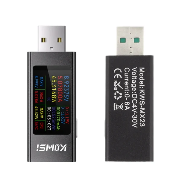 KWS-MX23 HD 1.06 inch IPS Display Multi-function USB Tester Voltage Ammeter Power Meter DC 4-30V 0-8A USB Tester Multimeter
$8.90
KWS-MX23 HD 1.06 inch IPS Display Multi-function USB Tester Voltage Ammeter Power Meter DC 4-30V 0-8A USB Tester Multimeter
$8.90
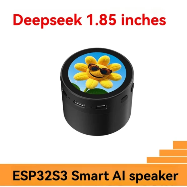 For DeepSeek XiaoZhi AI Voice Chat Speaker Box ESP32-S3 N16R8 Development Board with 1.85 Inch Round LCD Display
$39.90
For DeepSeek XiaoZhi AI Voice Chat Speaker Box ESP32-S3 N16R8 Development Board with 1.85 Inch Round LCD Display
$39.90
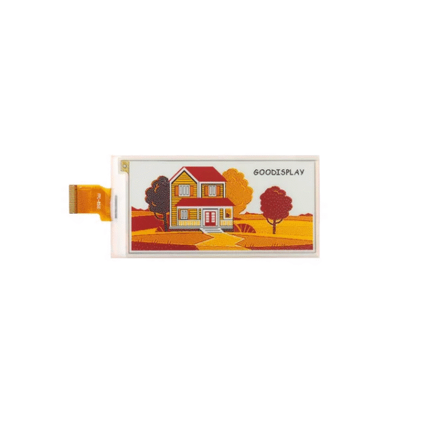 3.5 Inch 4-Color E-Ink Display 384x184 SPI Interface E-Paper Module
$16.90 – $34.90Price range: $16.90 through $34.90
3.5 Inch 4-Color E-Ink Display 384x184 SPI Interface E-Paper Module
$16.90 – $34.90Price range: $16.90 through $34.90
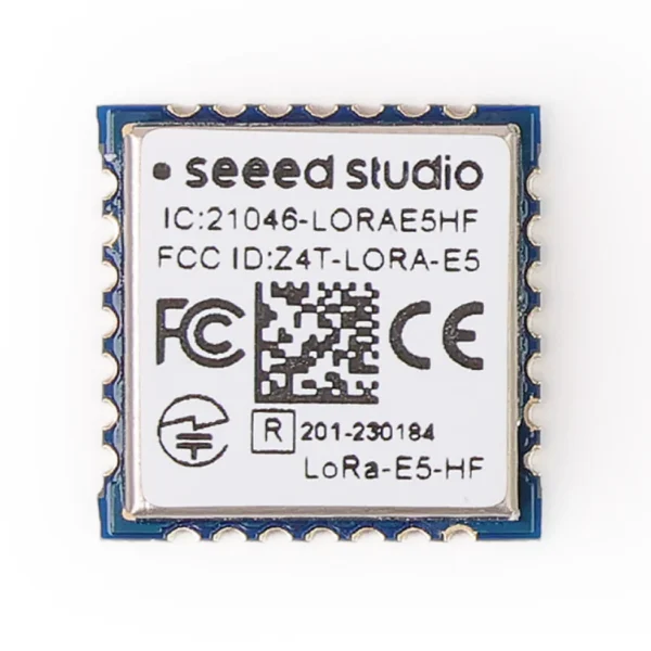 Lora Module 868mhz 915mhz Receiver and Transmitter- Wio E5 Wireless Module(Bulk &Tape Reel)-STM32WLE5JC,ARM Cortex-M4 and SX126x
$15.90
Lora Module 868mhz 915mhz Receiver and Transmitter- Wio E5 Wireless Module(Bulk &Tape Reel)-STM32WLE5JC,ARM Cortex-M4 and SX126x
$15.90
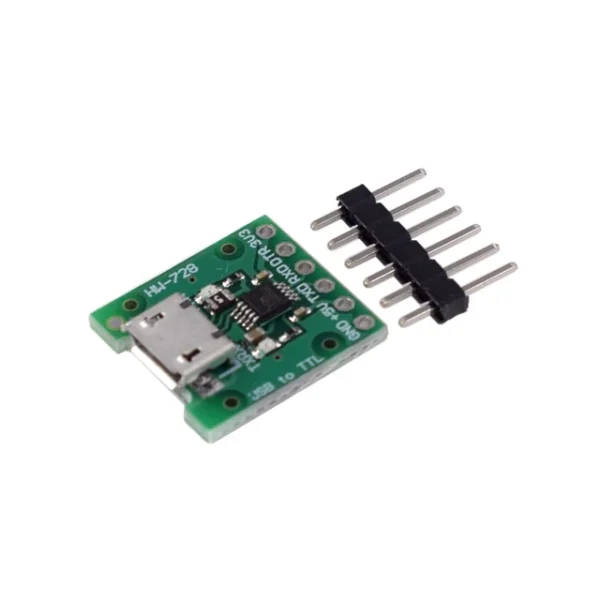 CH340E MSOP10 USB to TTL Serial Converter, 5V/3.3V Alternative CH340 E Module Micro USB Interface For Arduino Pro mini
$1.90
CH340E MSOP10 USB to TTL Serial Converter, 5V/3.3V Alternative CH340 E Module Micro USB Interface For Arduino Pro mini
$1.90
EMC testing is expensive, and failing it is worse than the test fee — it costs you a respin, a
We review a lot of boards — some designed in-house, some by other contractors, some by founders doing their own
When a battery-powered product dies too soon, the instinct is to blame the firmware. Surely there is a sleep mode
A wearable PCB is not just a small PCB. It is a board where every constraint that normally has some
The STM32 family is the workhorse of embedded hardware, and almost every project that uses one starts the same way:
The nRF52840 is one of the most popular BLE and multiprotocol chips in the world, and for good reason: it
No account yet?
Create an Account