EMC/EMI Checklist Before Your Board Goes to Certification
EMC testing is expensive, and failing it is worse than the test fee — it costs you a respin, a
The ESP32 microcontroller is a powerhouse for IoT and embedded systems projects, renowned for its robust feature set and wireless capabilities. One of its most fundamental and powerful tools for interacting with the analog world is Pulse Width Modulation, or PWM.
While a digital pin can only be ON (5V/3.3V) or OFF (0V), many components like LEDs, servos, and motors require variable voltage or precise timing for control. This is where the ESP32's PWM capabilities excel. This tutorial will provide an in-depth exploration of how to harness the ESP32's PWM functionality, from basic concepts to advanced implementation.
Pulse Width Modulation is not a true analog signal. Instead, it is a digital technique to simulate an analog result by rapidly switching a digital signal on and off. The key parameters are:
Frequency: The number of complete on/off cycles per second (Hz). A higher frequency means the cycle repeats faster.
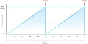
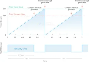
Duty Cycle: The percentage of one period where the signal is HIGH (ON). A 0% duty cycle is always OFF, a 100% duty cycle is always ON, and a 50% duty cycle is ON half the time.
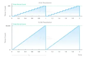
Resolution: The precision with which the duty cycle can be set. It is expressed in bits. A higher resolution allows for finer control over the pulse timing.
The average voltage delivered to a load is directly proportional to the duty cycle. By varying the duty cycle, we effectively control the average power. 
Unlike simpler microcontrollers (e.g., Arduino UNO) which may have a limited number of hardware PWM pins, the ESP32 is incredibly flexible. Its key features include:
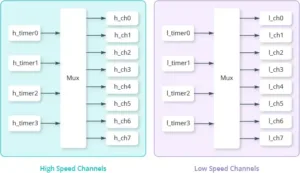
Dedicated LED PWM Controller: The ESP32 has a dedicated hardware module specifically for generating PWM signals, ensuring consistent and glitch-free operation without CPU intervention.
High Resolution: It supports up to 16-bit resolution, allowing for extremely fine control (65,536 discrete duty cycle levels).
High Frequency: It can generate signals with frequencies up to tens of kHz, which is essential for applications like driving brushless DC motors or switching power supplies efficiently.
Pin Flexibility: Almost any GPIO pin can be configured as a PWM output, providing tremendous design flexibility.
The Arduino IDE analogWrite() function is not natively available for ESP32 in the same way. Instead, we use the ESP32-specific LED Control (LEDC) functions.
The setup process involves two main steps: configuration and output.
ledcSetup())Before outputting a signal, you must set up a PWM channel with your desired frequency and resolution.
cpp
ledcSetup(channel, frequency, resolution_bits);
channel: The LEDC channel (0-15) to configure.
frequency: The desired PWM frequency (e.g., 5000 for 5 kHz).
resolution_bits: The resolution in bits (1-16, e.g., 8 bits for 256 steps).
ledcAttachPin())This function links the configured channel to a specific physical GPIO pin.
PWM_pin: The GPIO pin you want to use as PWM output (e.g., GPIO 16).
channel: The channel number you configured in Step 1.
ledcWrite())This function outputs the PWM signal with the specified duty cycle to the attached pin.
ledcWrite(channel, duty_value);
channel: The channel number.
duty_value: An integer value between 0 and (2^resolution - 1). For 8-bit resolution, this is 0-255.
Let's put theory into practice by creating a classic fading LED effect.
LED
220Ω Resistor
Breadboard and Jumper Wires
Connect the anode of the LED (long leg) through the 220Ω resistor to GPIO 16. Connect the cathode (short leg) to GND.
// Define the PWM Channel, GPIO Pin, and PWM parameters
const int pwmChannel = 0; // Select PWM channel 0
const int pwmPin = 16; // GPIO 16 for PWM output
const int freq = 5000; // PWM frequency of 5 KHz
const int resolution = 8; // 8-bit resolution (duty cycle 0-255)
void setup() {
// Configure the PWM functionalit
ledcSetup(pwmChannel, freq, resolution);
// Attach the channel to the GPIO pin
ledcAttachPin(pwmPin, pwmChannel);
}
void loop() {
// Increase LED brightness gradually
for (int dutyCycle = 0; dutyCycle <= 255; dutyCycle++) {
ledcWrite(pwmChannel, dutyCycle);
delay(10);
}
// Decrease LED brightness gradually
for (int dutyCycle = 255; dutyCycle >= 0; dutyCycle--) {
ledcWrite(pwmChannel, dutyCycle);
delay(10);
}
}
This code will smoothly fade the LED on and off by incrementally changing the duty cycle.
The utility of PWM extends far beyond dimming lights:
Servo Motor Control: Servos use PWM pulses of a specific duration (typically 1-2ms) within a 20ms period to determine their angle. The ESP32's high resolution allows for very precise servo positioning.
DC Motor Speed Control: Coupled with an H-Bridge motor driver IC (like the L298N), PWM is the standard method for controlling the speed and direction of DC motors.
Audio Generation: By generating PWM signals at audio frequencies (20Hz - 20kHz) and filtering the output with a low-pass filter, the ESP32 can synthesize simple tones and sounds.
Power Regulation: PWM is the cornerstone of modern switched-mode power supplies (SMPS) and voltage regulators, allowing for highly efficient power conversion.
Mastering Pulse Width Modulation is a critical skill for anyone working with the ESP32. Its dedicated hardware, high resolution, and pin flexibility make it superior to many other microcontrollers for generating precise digital control signals. By understanding the ledcSetup(), ledcAttachPin(), and ledcWrite() functions, you can unlock a world of possibilities, from creating simple lighting effects to building complex robotic systems. Integrate these techniques into your next ESP32 project to achieve professional-grade control over analog devices.
======================================
5V 2A 1x 18650/21700 USB Type-C Battery Charger Case DIY Power Bank Box For Phone Electronic Charging Not Including Batteries
$2.90
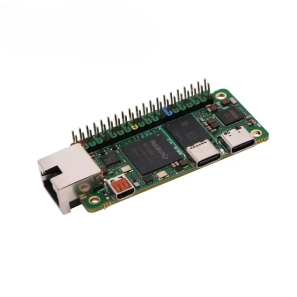
Radxa ZERO 3E RK3566 4-core CPU SBC, GPU, NPU, HDMI with 1080P Output, and Gigabit Ethernet, Single Board with Pin Header
$98.60 – $186.90Price range: $98.60 through $186.90
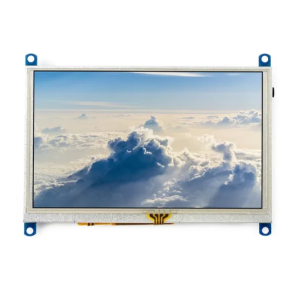
5inch Resistive Touch Screen LCD G 800x480 Display Computer Monitor Supports Raspberry Pi/BB Black/Banana Pi/Orange Pi
$49.80
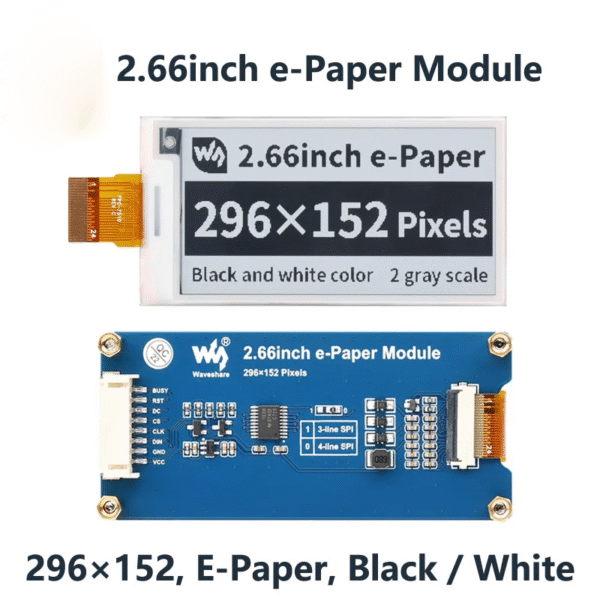
2.66 inch E-Paper E-Ink Display Module For Arduino/Raspberry Pi/STM32
$12.70
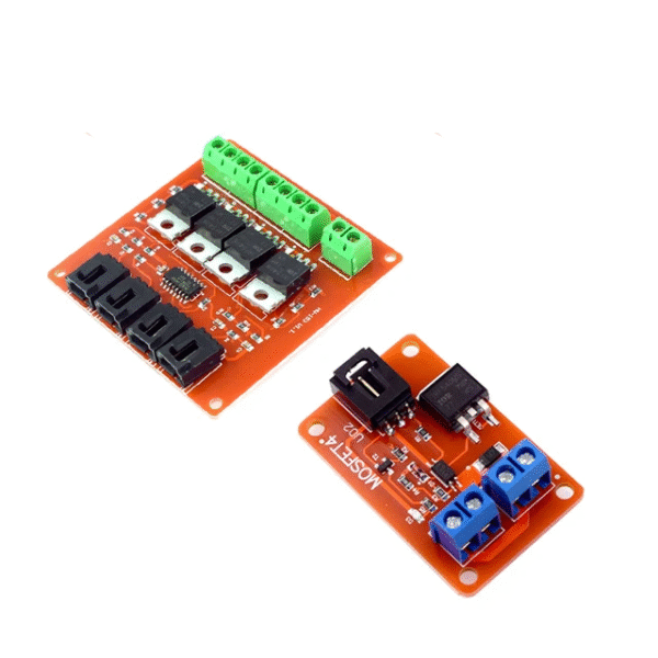
1 / 4 Channel one Four Route MOSFET Button IRF540 V4.0+ MOSFET Switch Module for Arduino Isolated power module
$2.90 – $3.90Price range: $2.90 through $3.90
EMC testing is expensive, and failing it is worse than the test fee — it costs you a respin, a
We review a lot of boards — some designed in-house, some by other contractors, some by founders doing their own
When a battery-powered product dies too soon, the instinct is to blame the firmware. Surely there is a sleep mode
A wearable PCB is not just a small PCB. It is a board where every constraint that normally has some
The STM32 family is the workhorse of embedded hardware, and almost every project that uses one starts the same way:
The nRF52840 is one of the most popular BLE and multiprotocol chips in the world, and for good reason: it
No account yet?
Create an Account