
EMC/EMI Checklist Before Your Board Goes to Certification
EMC testing is expensive, and failing it is worse than the test fee — it costs you a respin, a
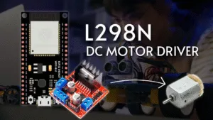
Embarking on an electronics project that involves movement? Controlling a DC motor is a fundamental skill, and pairing the powerful ESP32 microcontroller with the versatile L298N motor driver module is a perfect combination for the task. This comprehensive tutorial will guide you through the hardware connections and software programming needed to manage both the speed and spinning direction of a DC motor.
The ESP32 is a feature-rich, Wi-Fi and Bluetooth-enabled microcontroller that acts as the brain of your operation. However, its GPIO pins cannot supply enough current to drive a motor directly. This is where the L298N driver module comes in.
The L298N is a dual H-bridge motor controller. Think of it as a powerful middleman between your delicate ESP32 and the power-hungry motor. It can:
Control Direction: By activating specific switches (transistors) inside its H-bridge circuit, it can reverse the polarity of the voltage applied to the motor, making it spin clockwise or counter-clockwise.
Control Speed: Using a technique called Pulse Width Modulation (PWM), it can rapidly switch the motor's power on and off to simulate variable voltage, effectively changing its speed.
ESP32 Development Board (e.g., ESP-WROOM-32)
L298N Motor Driver Module
1 x DC Motor (6V to 12V is ideal)
External Power Supply (e.g., 9V battery or 12V adapter)
Jumper Wires (Male-to-Female and Male-to-Male)
Breadboard
1. Power Connections:
Motor Power: Connect the positive terminal of your external battery (+12V on the L298N) and the ground to the (GND) terminal. This powers the motor itself. Important: Remove the jumper pin from the ENA pin and the 5V Enable jumper if your supply voltage is greater than 12V. This disconnects the onboard 5V regulator.
ESP32 Power: Connect the GND of the L298N to the GND of the ESP32. This creates a common ground, which is crucial for the circuit to work correctly.
2. Motor Outputs:
Connect your DC motor's two wires to the OUT1 and OUT2 terminals on the L298N module.
3. Control Pins:
Connect the ENA (Enable A) pin on the L298N to GPIO D13 on the ESP32. This pin will control the speed via PWM.
Connect the IN1 pin to GPIO D12 and the IN2 pin to GPIO D14. These pins will control the motor's direction.
The code below initializes the control pins and provides functions to run the motor in different directions at various speeds.
// Define the ESP32 GPIO pins connected to the L298N
const int enA = 13; // PWM pin for speed control
const int in1 = 12;
const int in2 = 14;
// PWM properties for ESP32 (LEDC channel, frequency, resolution)
const int pwmChannel = 0;
const int freq = 30000;
const int resolution = 8; // 8-bit resolution (0-255)
void setup() {
// Set the control pins as outputs
pinMode(in1, OUTPUT);
pinMode(in2, OUTPUT);
pinMode(enA, OUTPUT);
// Configure the ESP32's LEDC PWM functionality
ledcSetup(pwmChannel, freq, resolution);
ledcAttachPin(enA, pwmChannel);
// Initially, turn the motor off
digitalWrite(in1, LOW);
digitalWrite(in2, LOW);
}
void loop() {
// Function calls to demonstrate motor control
clockwiseDirection();
delay(2000);
stopMotor();
delay(500);
counterClockwiseDirection();
delay(2000);
stopMotor();
delay(500);
speedRamp();
delay(2000);
}
void clockwiseDirection() {
digitalWrite(in1, HIGH);
digitalWrite(in2, LOW);
ledcWrite(pwmChannel, 200); // Set speed to ~200/255
}
void counterClockwiseDirection() {
digitalWrite(in1, LOW);
digitalWrite(in2, HIGH);
ledcWrite(pwmChannel, 200); // Set speed to ~200/255
}
void stopMotor() {
digitalWrite(in1, LOW);
digitalWrite(in2, LOW);
ledcWrite(pwmChannel, 0); // Set speed to 0
}
void speedRamp() {
digitalWrite(in1, HIGH);
digitalWrite(in2, LOW);
// Gradually increase speed from 0 to max
for (int dutyCycle = 0; dutyCycle <= 255; dutyCycle++) {
ledcWrite(pwmChannel, dutyCycle);
delay(20);
}
// Gradually decrease speed from max to 0
for (int dutyCycle = 255; dutyCycle >= 0; dutyCycle--) {
ledcWrite(pwmChannel, dutyCycle);
delay(20);
}
}
Direction Control: Setting IN1 = HIGH and IN2 = LOW makes the motor spin in one direction. Reversing these logic levels (IN1 = LOW, IN2 = HIGH) reverses the motor.
Speed Control: The ledcWrite() function generates a PWM signal on the ENA pin. A value of 0 is stop, and 255 is full speed. The speedRamp() function demonstrates how to smoothly change the speed.
Motor Doesn't Spin: Double-check all wiring, especially the common ground between the ESP32 and the L298N. Ensure the external battery is charged.
L298N Module Gets Hot: The L298N has a significant voltage drop and can get warm during operation. For high-current motors, consider using a heatsink or a more efficient driver like a TB6612FNG.
Jumpy Motor at Low Speed: PWM frequency might be too low. The code uses 30 kHz, which is often better for motor control than the default 490 Hz, as it reduces audible noise.
This setup forms the foundation for countless projects, from simple robots and car kits to automated curtains and conveyor belts. By mastering this, you unlock a world of possibilities for adding motion to your IoT creations.
======================================

No account yet?
Create an Account